JAI EL-2800M-CXP, User Manual
The JAI EL-2800M-CXP is an advanced camera that delivers exceptional image quality and high-speed performance. To understand its full potential and features, make sure to download the comprehensive user manual for free from our website. Unlock the camera's capabilities with this indispensable manual available at manualshive.com.
Share
Download


Reviews:
No comments
Related manuals for EL-2800M-CXP

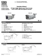
48 Series
Brand: Safety Vision Pages: 24

X64
Brand: IDS Pages: 36

W7
Brand: Wansview Pages: 12

MD30
Brand: Vaisala Pages: 7

951-197
Brand: Kayoba Pages: 44

D-IPC-HDW3449HP-AS-PV-0280B
Brand: Dahua Pages: 20

MDC845
Brand: ADT Pages: 29

PIH-0364X WN IP
Brand: Lilin Pages: 29

IC-1500 series
Brand: Edimax Pages: 11

GV-LPR CAM V2.0 Series
Brand: GeoVision Pages: 4

O3VFDM
Brand: Speco Pages: 13

WV-U2130LA
Brand: i-PRO Pages: 16

GLASS BREAK DETECTOR
Brand: Tattletale Pages: 2

10551
Brand: NA-DE Pages: 7
EIR48X-42VF
Brand: Okina Pages: 4

HP-BLU Series
Brand: Gentec-EO Pages: 28

IPC-100AC-AUS
Brand: MAGINON Pages: 64

F004
Brand: Tamron Pages: 2


