JAI CV-M40, Operation Manual
The JAI CV-M40 is a high-performance camera with exceptional image quality. Enhance your understanding of its features and functions by downloading the free Operation Manual from our website. Accessible and easy-to-follow, this manual is a valuable resource for maximizing the potential of your JAI CV-M40 camera.
Share
Download


Reviews:
No comments
Related manuals for CV-M40

LAD-SAF
Brand: 3M Pages: 88

HomeGuard 32
Brand: Mami Pages: 16

10220
Brand: NA-DE Pages: 8

IC 1285 Z
Brand: Olympia Pages: 92
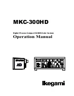
MKC-300HD
Brand: Ikegami Pages: 35

The Protector NW308
Brand: Nationwide Industries Pages: 2

E2xC1LD2F
Brand: E2S Pages: 12

G50CC
Brand: Gator Pages: 2

ERB-L747N
Brand: Eyeris Pages: 10

Rescue Pro PFD
Brand: IONIC Pages: 12

CGAS-A-VLT-NH3-S
Brand: Critical Environment Technologies Pages: 20

1L-HD-LP-100
Brand: Avigilon Pages: 28
WCB-00116
Brand: WingScapes Pages: 24

XCM4040SAT2
Brand: NED Pages: 72

water guardian
Brand: QMI Pages: 10

SafeScout
Brand: Sentinel Pages: 16

APPCAM 24HD
Brand: Uniden Pages: 36

Memory Camera Series
Brand: Swann Pages: 8


