background image

Installation Guide

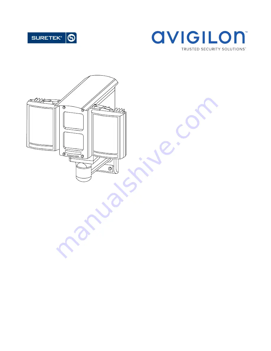
Avigilon™ License Plate Recognition System Models:

1L-HD-LP-35, 1L-HD-LP-50, 1L-HD-LP-75, 1L-HD-LP-100 and 2L-
HD-LP-40

 SUPPORT  [email protected]  |  1300 65 44 33  |  suretek.com.au

Summary of Contents for 1L-HD-LP-100

Page 1: ...Installation Guide Avigilon License Plate Recognition System Models 1L HD LP 35 1L HD LP 50 1L HD LP 75 1L HD LP 100 and 2L HD LP 40 SUPPORT ipvideo suretek com au 1300 65 44 33 suretek com au ...

Page 2: ...opia del presente manuale nel propria lingua fare riferimento alla Guida di progettazione ed installazione Avigilon LPR nel Avigilon centro risorse l DE Eine Kopie dieses Handbuchs in Ihrer bevorzugten Sprache finden Sie im Avigilon Resource Center unter Avigilon LPR Design und Installationsanleitung l PT BR Para obter uma cópia deste manual em seu idioma preferido veja o Guia de projeto e instala...

Page 3: ...n trademark patent or other intellectual property rights of Avigilon Corporation or its licensors This document has been compiled and published covering the latest product descriptions and specifications The contents of this document and the specifications of the products discussed herein are subject to change without notice Avigilon Corporation reserves the right to make any such changes without ...

Page 4: ...LPR Enclosure 13 Mounting the Power Supply Unit 15 PSU Cable Connections 15 PSU to LPR Kit Connections 15 Connecting Cables in the PSU 16 Positioning the HD LPR Capture Kit 18 Adjusting the Mounting Bracket 18 Adjusting the Enclosure 19 Configuring LPR in the ACC Software 21 Configuring the Camera 21 Setting Up License Plate Recognition 22 Configuring the Watch List 22 Adding Licenses to the Watch...

Page 5: ...Performing a License Plate Search 24 Viewing Search Results 24 Verification Test 26 Specifications 27 Limited Warranty Technical Support 28 5 ...

Page 6: ...w to select an appropriate LPR camera model and mounting location see Site Design on the next page For information on how to install and position the HD LPR Capture Kit see Installation on page 11 For information on how to use the License Plate Recognition feature in the AvigilonControl Center ACC see Configuring LPR in the ACC Software on page 21 Introduction 6 ...

Page 7: ...ers The Avigilon HD LPR Capture Kit is designed to cover a single traffic lane of 10 ft 3m or two adjacent traffic lanes The maximum number of lanes that can be monitored on a single server depends on the target vehicle speed and the mounting height Speed mph km h Maximum number of lanes per NVR Recommended Overhead Maximum number of lanes per NVR Maximum Overhead or Roadside 0 20 0 32 4 2 20 30 3...

Page 8: ...unted directly above the vehicle path Refer to the following tables for recommended and maximum mounting heights for each HD LPR Capture Kit model and their corresponding horizontal distances to the license plate detection area Overhead Recommended Mounting Height HD LPR Capture Kit Target Distance ft m Recommended Mounting Height ft m Horizontal Distance ft m 1L HD LP 35 35 11 9 12 2 8 3 6 33 10 ...

Page 9: ...istance for each HD LPR Capture Kit model Select the shortest target distance that results in a practical mounting location NOTE The dual lane kit 2L HD LP 40 should not be mounted in the roadside position Roadside Mounting Height and Offset HD LPR Capture Kit Target Distance ft m Max Mounting Height ft m Max Offset ft m Horizontal Distance ft m 1L HD LP 35 35 11 12 3 6 12 3 6 32 10 1L HD LP 50 50...

Page 10: ...re Gauge vs Max Distance Wire Gauge AWG Max Distance m ft 18 4 0 13 20 2 5 8 4 22 1 6 5 3 24 1 0 3 3 Field Of View The camera field of view is the area that is visible in the video image When a moving vehicle is not in the field of view it is important that the LPR camera is not aimed at anything that could be interpreted as a series of alphanumeric characters such as a billboard or road sign The ...

Page 11: ...Steps Complete the following steps to install the device Connecting Cables to the Camera Important Do not adjust the LPR camera inside the enclosure It is calibrated for a specific target distance CAUTION Do not tilt the enclosure backwards when the back panel is removed The camera may slide out 1 Loosen the four screws at the back of the enclosure and remove the back panel 2 To add an overview ca...

Page 12: ...losure and remove the back panel 2 Remove the network cables from the terminals labeled J8 CAT5 and J9 CAT5 3 Slide out the metal mounting plate below the LPR camera Be careful not to touch the LPR camera or lens 4 Use the provided UNC 20 bolt and camera adapter to attach the overview camera to the mounting plate 5 Slide the mounting plate and overview camera into the enclosure Ensure that the bol...

Page 13: ... camera connect the terminal labeled J2 Power Camera 1 to the power connector block of the LPR camera 2 To connect power to the overview camera connect the terminal labeled J3 Power Camera 2 to the power connector block of the overview camera Mounting the LPR Enclosure Before you can mount the HD LPR Capture Kit you must choose a mounting location For more information see Site Design on page 7 Com...

Page 14: ...et to the mounting surface l Use screws that are appropriate for the mounting surface l It is recommended that you apply silicone sealant into the mounting holes underneath the screw heads 3 Use the provided 3mm Hex key to remove the four screws from the base of the enclosure Mounting the LPREnclosure 14 ...

Page 15: ...m the LPR kit For more information see Maximum Cable Length on page 10 Install the PSU within the maximum distance using the four M4 mounting holes at each corner of the unit Do not connect power to the PSU until all other cable connections have been established PSU Cable Connections PSU to LPR Kit Connections The HD LPR Capture Kit is powered and connected to the network through the PSU Mounting ...

Page 16: ...ork cable from switch for LPR camera 4 Network cable from switch for optional overview camera 5 Power supply cable to PSU Connecting Cables in the PSU Refer to the following diagram for the locations of the different connectors Connecting Cables in the PSU 16 ...

Page 17: ... the diagram b Connect the red and black wires to J4 Lamp Power o Red positive o Black negative c Connect the purple and white wires to J8 15 V Aux Power o Purple positive o White negative 2 Connect the gray network cable from the LPR camera to the PSU a Pull the cable through the second cable gland 2 in the diagram b Connect the wires to the appropriate terminals in the punch down block labeled J...

Page 18: ...ommended that you use a 24 V secondary 100 VA transformer a Pull the cable through the fifth cable gland 5 in the diagram b Connect the red and black wires to J6 Low Voltage AC DC Input terminal o Red positive o Black negative Tip If power is supplied to the PSU there will be a red glow from both IR panels You can verify this by taking a photo of the IR panels with a phone camera The red glow will...

Page 19: ...ar horizontal in the image 1 Park a vehicle in the center of the field of view 2 View the image of the vehicle If the image is horizontal you do not need to install the shims 3 If the vehicle s license plate is not horizontal in the image unscrew the 2 screws in the base of the enclosure on the side that needs to be corrected and replace them with shim mounting screws Do not tighten 4 Install a sh...

Page 20: ...5 Tighten the screws at the base of the enclosure Figure 5 Tilted license plate incorrect Figure 6 Horizontal license plate correct Adjusting the Enclosure 20 ...

Page 21: ...et the camera image rate based on the following table Speed mph km h Minimum Frame Rate ips installed at the recommended overhead mounting height Minimum Frame Rate ips installed at the maximum overhead or roadside mounting height 0 20 0 32 5 10 20 30 32 50 10 15 30 40 50 65 15 24 40 60 65 100 24 Not recommended To change the camera s image rate and quality complete the following steps 1 In the AC...

Page 22: ...nce required for a detected license plate to be recognized The default value is 80 l Enable this lane select this check box to enable LPR on this lane 4 Move and adjust the green overlay until it spans the width of the traffic lane in the camera s field of view LPR is only performed in the green area NOTE If the overlay is red the license plate detection area is too large and cannot be used 5 Clic...

Page 23: ... a comma separated values CSV file Importing a Watch List 1 In the License Plate Recognition dialog box select the Watch List tab 2 Click Import 3 In the Import dialog box locate the Watch List file and click Open Monitoring Detected License Plates After the LPR system has been installed you can use the ACC Client software to monitor license plates as they are detected To monitor license plates as...

Page 24: ... new license plates are detected Performing a License Plate Search 1 In the New Task menu click The Search License Plates tab is displayed 2 In the Camera s to Search area select all the cameras you want to include in the search 3 In the Time Range to Search area set the date and time range of your search The time range is highlighted on the Timeline by the black time range markers You can also dr...

Page 25: ...to display the search result video in a new View tab 7 To export all listed search results click Export results to a file and save the file The search results can be saved as either a CSV or Text file Viewing Search Results 25 ...

Page 26: ...ense plate characters 4 Drive a vehicle through the field of view of the LPR camera and check that the license plate was read correctly 5 Review each frame of the vehicle passing through the field of view The brightness of the license plate should peak as the vehicle passes the center of the field of view 6 Unblock the road and watch the LPR camera capture actual traffic Run a License Plate Search...

Page 27: ...ator Dimensions LxWxH 160 x 160 x 81 mm 6 3 x 6 3 x 3 2 Weight 1 85 kg 4 1 lbs Mount 4 x M4 holes at 145 mm x 123 mm 5 71 x 4 85 Electrical Camera Power Source 24 VDC 24 VAC PoE IEEE802 3af Class 3 compliant Power Consumption 6 W per camera Power Connector 2 pin terminal block Illuminator Power Source 24 VDC 24 VAC Power Consumption 72 W Power Connector 3 wire terminal block 12 20 AWG Environmenta...

Page 28: ...ranty terms for this product is provided at avigilon com warranty Warranty service and technical support can be obtained by contacting Avigilon Technical Support avigilon com contact us 28 SUPPORT ipvideo suretek com au 1300 65 44 33 suretek com au ...

Reviews: