background image

CV-L105


6.2.4. External Trigger. Shutter mode. 

In this mode, the camera requires an EXT TRIG signal to be issued to the camera. The trigger 
signal is typical taken from an encoder. The scanning time is equal to the trigger interval. The 
exposure time is equal to the trigger low period (pulse width). For every EXT TRIG input negative 

going edge an integration period starts. It is terminated and charge is read out on the trigger 
positive going edge. The exposure time is therefore independant of the line rate. 
SHUTTER and SCAN parameters has no function here. 
The permitted range for the trigger interval is >2120 clk to 

.  

Max scan rate is 14285 lines per second. 
 
 
To use this mode: 

Set function: 

Trigger 

External 

     Mode 

SHUTTER 


SHUTTER value 

No function 


SCAN value 

No function 


Clock, Binning and other functions 


Input:   


Ext. trigger through the LVDS connector  


Important notes on using this mode:

-


• 

It is only recommended to use this mode when there is not change of speed in the object 

being scanned. If the speed of the object changes, the exposure time change. 

• 

Do not apply a new trigger before the previous result has been read out. >2120 clk. 
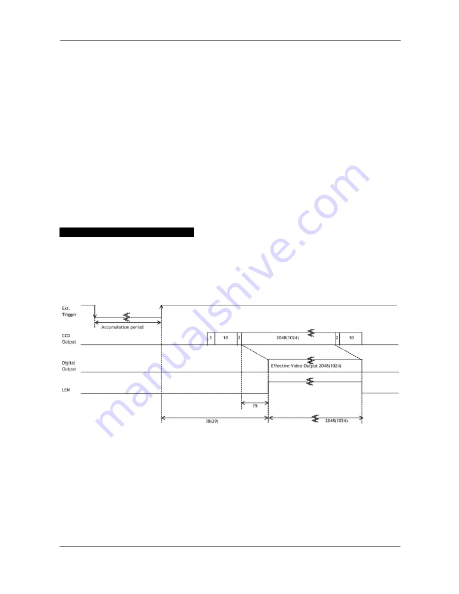


30 MHz  1t=33.3 ns 
15 MHz   1t=66.6 ns 
Value in ( ) is for Binning


Fig. 15. Timing for external trigger shutter mode 


- 13 -


Summary of Contents for CV-L105

Page 1: ...3CCD High Speed Color Line Scan Camera CV L105 Operation Manual Camera Revision A Manual Version 1 1 CV L105manJan9 doc JPT 9 01 03 ...

Page 2: ...Scan mode 10 6 2 2 Internal Trigger Shutter mode 11 6 2 3 External Trigger Scan mode 12 6 2 4 External Trigger Shutter mode 13 6 3 Other functions 14 6 3 1 Binnig 14 6 3 2 Pixel rate 14 6 3 3 RS 232C on off 14 6 3 4 Offset and Gain 14 6 3 5 LED on rear 14 7 Configuring the Camera 15 7 1 RS 232C control 15 7 1 1 Clock Select 16 7 1 2 Binning 16 7 1 3 Trigger Mode 16 7 1 4 Shutter Scan Mode 16 7 1 5...

Page 3: ...can be downloaded from www jai com For camera revision history please contact your local JAI distributor 2 Standard Composition The standard camera composition consists of the camera main body 3 Main Features 3CCD prism based architecture 3 x 2048 pixels 14 µm x 14 µm User selectable pixel rate 15 or 30 MHz Internal or external triggered scanning Pulse interval and pulse width exposure control Sca...

Page 4: ... out 16 GD2 out 50 GD2 out 17 GD1 out 51 GD1 out 18 GD0 out Green Data out LVDS 52 GD0 out Green Data out LVDS 19 EXT TRIG in LVDS in 53 EXT TRIG in LVDS in 20 BD7 out 54 BD7 out 21 BD6 out 55 BD6 out 22 BD5 out 56 BD5 out 23 BD4 out 57 BD4 out 24 BD3 out 58 BD3 out 25 BD2 out 59 BD2 out 26 BD1 out 60 BD1 out 27 BD0 out Blue Data out LVDS 61 BD0 out Blue Data out LVDS 28 NC 62 NC 29 GND 63 GND 30 ...

Page 5: ...A 7R 6P Male The mating connector to use on the cable side is Hirose HR10A 7P 6S 5 3 9 pin DSUB connector RS 232C 2 3 4 5 6 7 8 6 1 2 2 3 3 4 4 5 5 6 6 7 7 8 8 6 6 1 1 Fig 4 9 pin DSUB for RS 232C Seen from camera rear Pin no Signal Remarks 1 NC 2 TXD To PC 3 RXD From PC 4 NC 5 GND 6 NC 7 NC 8 NC 9 NC The connector on the camera is a 9 pin DSUB male connector The cable to the PC is a straight thro...

Page 6: ...tput GD0 to GD7 Bits 0 to 7 positive side of the differential signal GD0 to GD7 Bits 0 to 7 negative side of the differential signal Blue channel video output BD0 to BD7 Bits 0 to 7 positive side of the differential signal BD0 to BD7 Bits 0 to 7 negative side of the differential signal Bit 0 is LSB Bit 7 is MSB STROBE This signal is used to latch the digital video into the frame grabber LEN Line e...

Page 7: ...r no binning For configuration please refer to 7 2 and 7 3 5 4 4 Pixel rate select input This input on pin 31 internal jumper JP 5 open and RS232C disabled allows external equipment such as a frame grabber PLD or similar to select the pixel rate The input circuit accepts TTL levels It has 4 7 kΩ pull up to 5V Open for 30 MHz For configuration please refer to 7 2 and 7 3 5 4 5 RS 232C on off enable...

Page 8: ...the vertical direction of the image Area Fig 8 The principle of line scan A 3CCD line scan camera follows the exact same principle with the added complexity of three CCD sensors mounted on a dichroic prism The three CCD sensors are aligned on the prism in such as way that they all view the same part of the object This is referred to as co site sampling Figure 4 shows the construction of the prism ...

Page 9: ...l and horizontal resolution The horizontal resolution is given by the number of pixels in the 3CCD camera The vertical resolution is given by the pulses generated by the encoder Example The width of the object to be scanned is 1000 mm This means that each pixel projected on the object represents a square of 0 488mm In order to maintain the same vertical resolution the encoder needs to generate 204...

Page 10: ...h 32 35 ms External Trigger Scan mode For every EXT TRIG input the ongoing integration period is terminated and charge is read out At the same time it starts a new cycle LEN Dataout Exposure Trigger Exposuretime LEN Dataout Exposure Trigger Exposuretime The exposure time is therefore dependant of the line rate SHUTTER and SCAN parameters has no meaning here Trigger pulse width high period 4 clk Tr...

Page 11: ...SHUTTER parameter has no function here To use this mode Set function Trigger Internal Mode SCAN SHUTTER value No function SCAN value 151 µs through 32 5 ms Clock Binning and other functions Input Important notes on using this mode It is only recommended to use this mode when there is not change of speed in the object being scanned If the speed of the object changes the aspect ratio in the vertical...

Page 12: ...ue is 1 µs up to SCAN time 150 µs Always less than SCAN To use this mode Set function Trigger Internal Mode SCAN SHUTTER value 1 µs up to 32 35 ms SCAN value 151 µs through 32 5 ms Clock Binning and other functions Input Ext trigger through the LVDS connector Important notes on using this mode It is only recommended to use this mode when there is not change of speed in the object being scanned If ...

Page 13: ...ted range for the trigger interval is 2120 clk to Max scan rate is 14285 lines per second Trigger width should be 4 clk To use this mode Set function Trigger External Mode SCAN SHUTTER value No function SCAN value No function Clock Binning and other functions Input Ext trigger through the LVDS connector Important notes on using this mode It is only recommended to use this mode when there is not ch...

Page 14: ...SCAN parameters has no function here The permitted range for the trigger interval is 2120 clk to Max scan rate is 14285 lines per second To use this mode Set function Trigger External Mode SHUTTER SHUTTER value No function SCAN value No function Clock Binning and other functions Input Ext trigger through the LVDS connector Important notes on using this mode It is only recommended to use this mode ...

Page 15: ...S 232C on off This function makes it possible to disable the RS 232C input It is useful when the camera is operated in an environment with RFI fields are present When RS 232C is disabled the binning and pixel rate can be changed by inputs on the I F connector The function can be selected by internal jumpers or on the I F connector pin 30 For configuration please refer to 7 2 and 7 3 6 3 4 Offset a...

Page 16: ... con PC COM PORT CAMERA TXD RXD GND 1 CD 4 DTR 6 DSR 2 RXD 3 TXD 5 GND 7 RTS 8 CTS 9 CI 9 pin D con PC COM PORT CAMERA Fig 16 RS 232C cable JAI provides a comprehensive software configuration tool to configure the different functions of the camera The CV L105 Camera Control Tool for Windows 98 NT 2000 can be downloaded from www jai com For not released versions only from JAI Partner Site The contr...

Page 17: ...can time and Shutter Time need to be configured for proper operation in this mode In External mode the camera is configured to accept an EXT TRIG pulse See also 6 2 Trigger modes 7 1 4 Shutter Scan Mode With Internal trigger and Shutter Scan Mode in Shutter mode the camera will be set to expose for a pre defined period of time set by Shutter Time The scan interval or scan rate is set by Scan Time ...

Page 18: ...s The range of these settings is 0 255 7 1 7 Communication and files The communication between the PC and the camera is set up and controlled from the communication window The camera settings and configuration can be read into the 4 user areas in the camera EEPROM or to files from this window Settings stored in files can be read and transferred to the program and read into the camera For detailed ...

Page 19: ... O JP5 open for 30 MHz Pixel clock select by JP5 S H JP5 closed for 15 MHz H 31 high for 30 MHz Pixel clock select by I F pin 31 S O H x x H O L 31 low for 15 MHz RS 232C disabled Set by jumper pin O jumper open S jumper short H input high open 5V by the internal 4 7 kΩ pull up resistor L input low closed to GND x do not care 7 3 Potentiometers and jumpers placing There are 5 solder jumpers on the...

Page 20: ...CV L105 19 8 External Appearance and Dimensions Fig 22 Outlines ...

Page 21: ...ge Differential Signalling LVDS Based on NS DS90C032 Gain range 12 dB Trigger input EIA 644 LVDS Based on NS DS90C031 STROBE output for latching video into frame grabber EIA 644 LVDS LEN output valid video duration EIA 644 LVDS Trigger modes Continuous Pulse Width Control Edge Pre select Functions controlled by input signal on interface connector Pixel rate and binning RS 232C control enable disab...

Page 22: ...entioned in this manual are trademarks or registered trademarks of their respective owners JAI A S cannot be held responsible for any technical or typographical errors and reserves the right to make changes to products and documentation without prior notification JAI A S Denmark JAI Corporation Japan JAI America Inc USA Produktionsvej 1 2600 Glostrup German Industry Center 800 West Cummings Park C...

Reviews: