background image

DCF-S-0126-2

Japan Aviation Electronics Industry, Ltd.

Connector Div. Production Engineering Dept.

日本航空電子工業株式会社コネクタ事業部生産技術部

Number

番号

T700251

Page

6

11

JAE Connector Div. Proprietary.
Copyright (C) 2002, Japan Aviation Electronics Industry, Ltd.

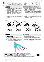
3.圧着準備

3.PREPARATION OF CRIMPING

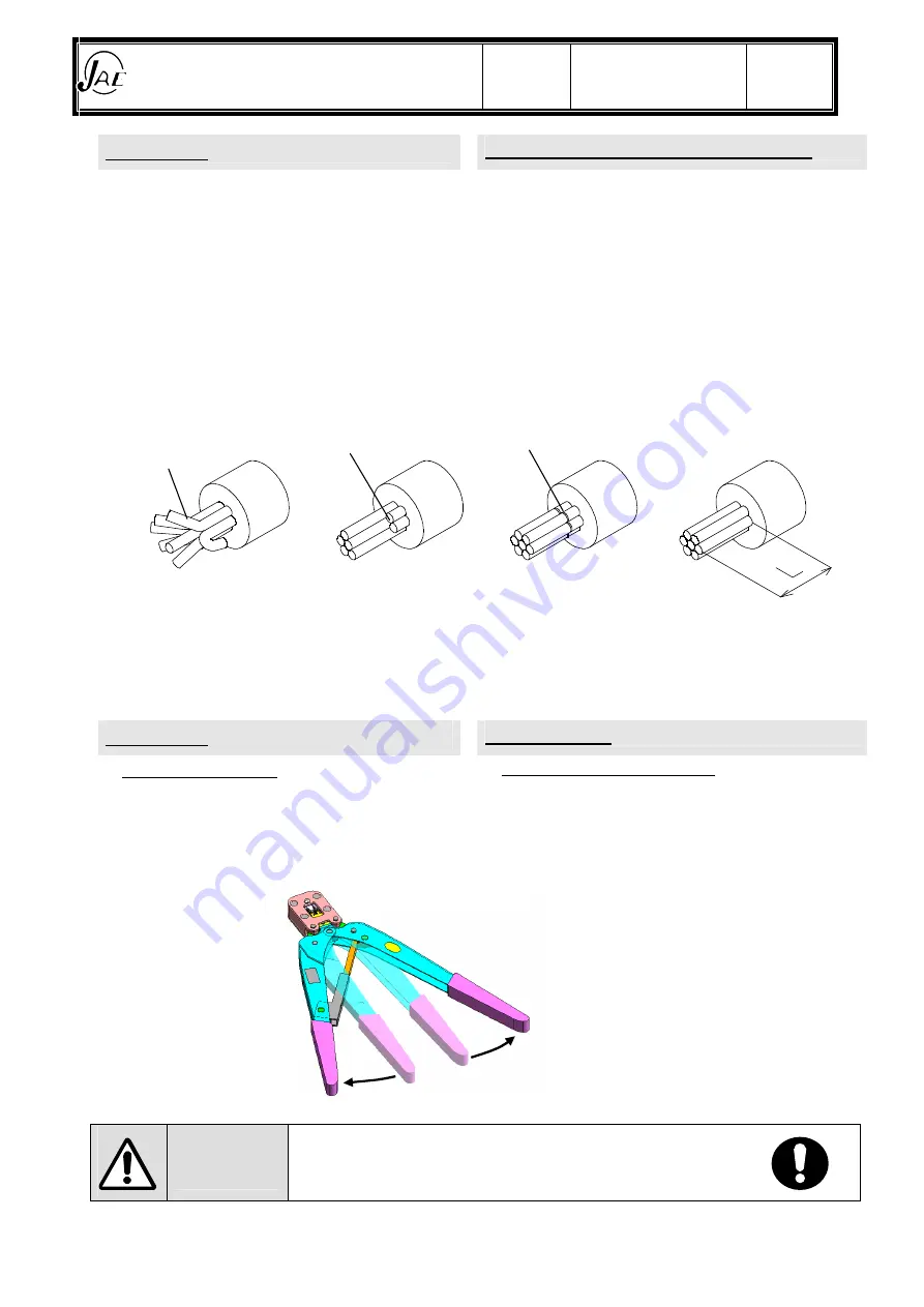
予め電線の被覆を指定剥き長さ(L寸法)で剥
いてください。(7項参照)

Strip the insulation of a wire to the specified
length

L

.

refer to para.7

芯線の切断、傷がないことを確認し、先端の
乱れは作業前に矯正して下さい。
芯線の切断、傷があったもの、先端の乱れが
矯正できないものは使用しないで下さい。

Check that each wire conductor is not damaged
nor scratched. Set any disarrayed conductors
straight prior to the crimping operation. Don't
use one with cutoff and the crack in the wick
line and the one that the disorder of the point
cannot be corrected.

圧着条件については、7 項.圧着条件を参照し
てください。

Refer to 7.the crimping condition about the
condition of crimping.

4.圧着作業

4.CRIMPING

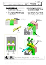
4-1.ハンドルの開放

4-1.HANDLES OPENING

① コンタクトを工具に挿入する前にハンドルを

開放状態にして下さい。

Open the handles before inserting a contact.

※ ハンドルが開かない場合は、ラチェットが開

放されるまでハンドルを握り締めて下さい。

In case the handle does not open, close the
handles until ratchet released.

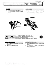
注意

CAUTION

アンビルが開閉します。怪我の原因となりますので、
クリンパとアンビルの間の隙間に指を入れないで下さい。

The crimper moves OPEN / CLOSE

Never put fingers into opening between the crimper and anvil

開放

OPEN

×

×

×

不良

Fail

不良

Fail

不良

Fail

良品

Pass

芯線の乱れ

Disordered wire strand

切断

Cut off

Crack

6/11

Summary of Contents for CT160-3B-MX23

Page 1: ...de S Kamimatsuse ISSUED Production Engineering Dept Prepared Checked Approved PL Approved Oikawa S Shimizu A Iwasaki T Abe JAE Connector Div Proprietary Copyright C 2002 Japan Aviation Electronics Ind...

Page 2: ...pecific warning information inside the lightning flash with arrowhead symbol shown left means a risk of electric shock to persons A no entry mark indicates an action that must be prohibited Inside or...

Page 3: ...pair it Please work while getting enough rest when you use this tool for a long time Injury might be caused for the body CAUTION Crimper and anvil can pinch the fingers Never put the fingers into spac...

Page 4: ...F HANDLING 3 CONTENTS 4 1 1 SPECIFICATION 5 2 2 PARTS NAME 5 3 3 PREPARATION OF CRIMPING 6 4 4 CRIMPING 6 4 1 4 1 HANDLES OPENING 6 4 2 4 2 CONTACT WIRE SETTING 7 4 3 4 3 CRIMPING 8 4 4 4 4 CONTACT RE...

Page 5: ...apan Aviation Electronics Industry Ltd 1 1 SPECIFICATION MODEL 160 3B MX23 WEIGHT 0 7 About 0 7kg SIZE W40 D33 5 H254 Environment 0 40 Temperature 0 40 No do be dewy The grip 300N CAUTION 300N This ha...

Page 6: ...any disarrayed conductors straight prior to the crimping operation Don t use one with cutoff and the crack in the wick line and the one that the disorder of the point cannot be corrected 7 Refer to 7...

Page 7: ...E SETTING Insert the contact into the locator along the anvil unit it hits the end stopper Incline the stripped wire as shown and lightly press the end against the wire stopper If the wire is inserted...

Page 8: ...holding the wire and contact position as set close the handles gradually with being careful not to misaligned until the ratchet is released In this stage crimping is completed CAUTION The crimper mov...

Page 9: ...PED CONTACT 1 7 2 1 Crimp height is satisfied with crimp standard refer to para 7 2 2 2 Wire strands tip is extended from the wire barrel 3 3 Wire insulation does not intrude into the wire barrel 4 4...

Page 10: ...e customer oneself of our hand tool resolve and oil it wears out Crimper and the Anvil etc if the tool is used for a long term and causes defective crimping We will at least recommend our company to s...

Page 11: ...ontact 1 Aplicable Cable Crimp height mm N Min Crimp Tensile Strength 2 Conductor 3 Insulation M23S05K351 AVSS 0 5 1 125 1 175mm 2 00 2 10mm 88 2N AVSS 0 85 127 4N AVSS 1 25 1 225 1 325mm 2 10 2 20mm...

Page 12: ...Mouser Electronics Authorized Distributor Click to View Pricing Inventory Delivery Lifecycle Information JAE Electronics CT160 3B MX23...

Reviews: