1 0 9 6 4 0
1 0 9 6 4 0
1
SPOUT ASSEMBLY
2
TEE AND HOSE ASSEMBLY
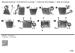
Note: All deck mounted Roman tub sets must be installed with the tub spout outlet at least two (2) inches above
the flood level rim of the tub. See Figure 1a.
Turn off hot and cold water
supplies before beginning.
CAUTION
2
1
4
5
5
1
3
2
10˚
6
6
7
7
FRONT
ROUGHING-IN
DIMENSIONS
Plumbers' Putty or Caulking
Adjustable Wrench
Phillips Screwdriver
Channel Locks
TOOLS REQUIRED
Tubing Cutter
Regular Screwdriver
Basin Wrench
1-1/4" MAX.
3/4"NPT
INLETS
NOTE : BORE SIZE 1-3/8"
1-1/8" D.
1-1/4" MAX.
Figure 1a
DECK MOUNT
BATH
RIM
BATH
RIM
TWO (2) INCHES
MINIMUM
TWO (2) INCHES
MINIMUM
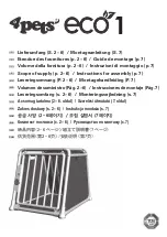
Make sure SHANK O-RING (1) is in place. Thread TEE (2)
onto end of SPOUT SHANK (3).
Rotate TEE (2) about10 degrees from center. Insert
COUPLING NUT (4) into TEE (2) and tighten on end of spout
shank to make a water tight connection. Do not over tighten.
Make sure SEAL WASHERS (5) are installed in HOSE ENDS (6).
Connect HOSE ENDS (6) of FLEX HOSE (7) to TEE (2).
Tighten securely.
MOUNTING
SURFACE
2" D.
8-1/4"
7/8" D.
12-3/8"
8-1/8"
KNOB
HANDLE
2" D.
4" TO 6"
4" TO 6"
2"
Assemble RUBBER WASHER (4) and LOCKNUT (5) onto SPOUT SHANK (3). Align SPOUT ASSEMBLY and from underside of ledge
secure SPOUT ASSEMBLY into position with LOCKNUT (5).
Install RING WASHER (1) into SPOUT BASE recess. Check that O-RING (2) on end of SPOUT SHANK (3) is in place. Insert SPOUT
SHANK (3) through center hole on mounting surface.
SPOUT BASE
RECESS
3
1
4
5
2
MOUNTING
SURFACE
(H)
(C)
COLD
15
12
13
14
Insert SEAL WASHERS (14) into COUPLING NUTS (15). Loop SUPPLY
HOSES (12) if required to avoid kinking. Tighten COUPLING NUTS (15) to
outlets of VALVE BODIES (9).
3
INSTALL VALVE BODIES AND HANDLES
INSTALL HANDLES
1-1/4'' MAX.
Thread LOCKNUT (8) to bottom of VALVE BODY (9). Make sure
FIBER WASHER (10) and RUBBER WASHER (11) are installed.
Insert VALVE BODY (9) through mounting hole from underside
of tub or mounting surface.
Note: VALVE BODY marked Hot is installed in the left mtg. hole,
VALVE BODY marked Cold in the right when facing front of fitting.
Maximum mounting surface thickness is 1-1/4".
From top install STOP RING (7). Thread LOCK RING (6) with seal washer
onto VALVE BODY (9) until tight against it's internal stop. Thread
ESCUTCHEON RING (5) onto VALVE BODY (9) until tight against it's
internal stop.
Set VALVE BODIES (9) so that their outlets are facing toward SPOUT
SHANK (13). Tighten LOCKNUT (8) using 35mm or adjustable
wrench to secure the valve bodies.
Thread counter-clockwise LEVER (1) from KNOB HANDLE (2) and
remove. With (2.5 mm) HEX WRENCH (3) (supplied) loosen
SET SCREW (4) and pull off handle from valve stem.
Remove ESCUTCHEON RING (5), LOCK RING (6) and STOP RING (7).
Note: Handle assemblies must be removed from valve bodies
before valve body installation.
HOT
JADO
MOUNTING
SURFACE
STEM
ADAPTER
HOT
1
3
4
10
11
5
6
7
8
9
2
Align LEVER HANDLES (1) as shown or as desired and
install HANDLE (2) onto STEM ADAPTER.
Tighten HANDLE SET SCREW (4) with (2.5mm)
HEX WRENCH (5) supplied to secure HANDLE.
Thread LEVER (1) into handle.