background image

5

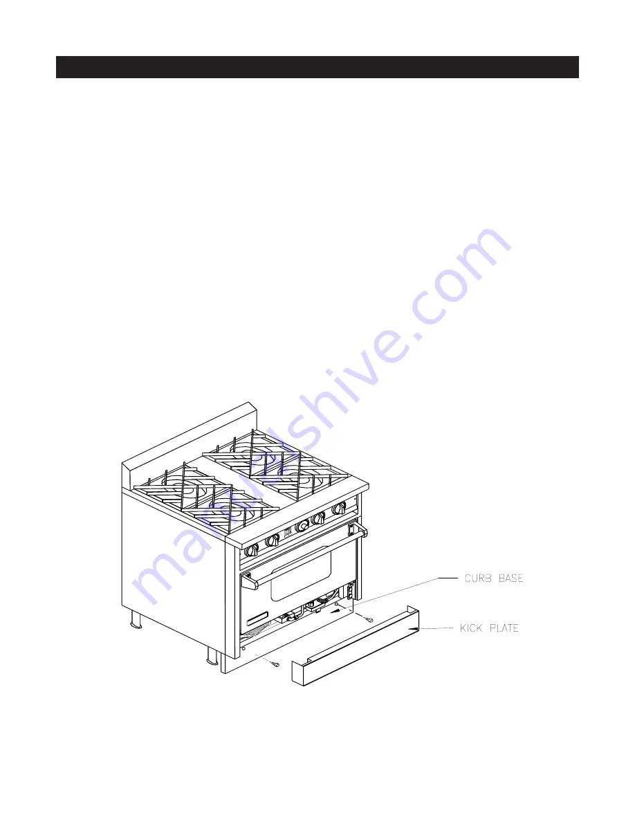
CURB BASE INSTALLATION

The curb base must be installed after the range has
been leveled and set properly in its final location.
To install the curb base, simply remove the kick plate
(the panel immediately below the oven door) and lo-
cate the mounting holes at the  front of the range base.
Secure the curb base to the front of the range base
using the two hexagonal sheet metals screws provided
with the curb base.  If the legs are adjusted to the
minimum height of 4 inches,  the curb base can have
0 to  1/8 gap between the floor.  When the legs are
adjusted higher, the gap can be as high as 2 inches
which may not be visually objectionable and not need
a filler.  If a filler is desired,  build a filler attached to the
floor or to the adjacent cabinets using screws or other
removable fasteners, so that the range can be readily
removed if necessary.

Summary of Contents for RJGR

Page 1: ...tallation Code This appliance must be electrically grounded in accordance with local codes or in the absence of local codes with the National Electrical Code ANSI NFA 70 latest edition In Canada it must be electrically grounded in accordance with local codes or with CSA C22 1 Canadian Electrical Code Part 1 P N 2400030000 06 03 WARNING If the information in this manual is not followed exactly a fi...

Page 2: ...ng make sure that the floor covering can withstand 90 F 65 C above room temperature without warping shrinking or discol oring Do not install the range over carpeting Remove unwrap and temporarily lay aside any part or accessory shipped with the unit and make sure that there are no hardware or accessories left in the box for accidental disposal Make sure all packing material and literature are remo...

Page 3: ...gher by turning the stainless steel adjustable feet using a 1 open end or adjustable wrench Adjust the legs so that the top of the range is even or higher than the counter top IMPORTANT NEVER SET THE RANGE LOWER THAN THE COUNTER TOP THE HEAT FROM THE TOP BURN ERS CAN DAMAGE THE COUNTER TOP For proper baking results it is important that the range is leveled To level the range 1 Use a 1 open end or ...

Page 4: ...vicing or clean ing the appliance However unlike the legs casters are not adjustable Any adjustment needed for level ing the range is accomplished by placing shims on the floor When checking to see if the range is level al ways use a spirit level or glass measuring cup placed on one of the racks It is extremely important for proper baking results that the racks are leveled When installing casters ...

Page 5: ...nt of the range base using the two hexagonal sheet metals screws provided with the curb base If the legs are adjusted to the minimum height of 4 inches the curb base can have 0 to 1 8 gap between the floor When the legs are adjusted higher the gap can be as high as 2 inches which may not be visually objectionable and not need a filler If a filler is desired build a filler attached to the floor or ...

Page 6: ...NGTHEGAS SUPPLYPIPEASSHOWN SECUREBOTTOMUSING4 SCREWS TOINSTALLSTUBBACK USESAMEPROCEDUREAS ISLANDBACK TOINSTALLHIGHSHELF 1 INSTALLHIGHSHELFFRONT 2 SECURETHESIDEFLANGES OFTHEFRONTUSINGBOLT ANDNUTONEACHEND 3 SECURETHEBOTTOMLIPOF THEFRONTAGAINSTTHEBACK OFTHERANGEUSING2 SCREWS 4SCREWSON DOUBLEOVENS 4 INSTALLBACKWITHTHEHOLE MATCHINGTHEGASSUPPLY PIPEASSHOWN SECUREBACK USING8SCREWS 5 HOOKHIGHSHELFTOTOPOF ...

Page 7: ...above the appliance should be main tained We recommend 30 distance from the bot tom of a standard ventilating hood made of sheet metal or noncombustible material to the range top surface Because of the high heat output of the Jade RJGR Gas Ranges a suitable exhaust hood must be installed above the range Because the design and efficiencies of the ventilating hoods vary from one manufacturer to anot...

Page 8: ...manifold pressure for natural gas is 5 wa ter column and for LP is 10 W C The gas supply line must be at least 1 W C above the manifold pressure and must not exceed 14 W C 3 5 kPa or 1 2 psig Installation of this range must conform with local codes Call the local gas supplier for the applicable codes in the area If there are no codes the installation must conform with the NATIONAL FUEL GAS CODE AN...

Page 9: ...ew orifice hood by carefully screwing it onto the valve or bi metal valve Follow proper orifice sizes indicated on chart below 5 Adjust air shutters for optimum burner performance WARNING IN ORDER TO AVOID A FIRE OR AN EXPLOSION CAUSING PROPERTY DAMAGE PERSONAL INJURY OR DEATH EXTRA PRECAUTION SHOULD BE TAKEN WHEN CONVERTING FROM NATURAL GAS TO LP PROPANE BY FOLLOWING CORRECT ORIFICE SIZES AS SPEC...

Page 10: ... RJGR SERIES FIGURE B TO FRONT OF OVEN SHUT OFF VALVE RANGE LIFT UP AS SHOWN FOR OPEN POSITION REGULATOR CAP CLOSED END EXPOSED IS SET FOR NATURAL GAS GAS INLET REGULATOR CAP OPEN END EXPOSED IS SET FOR LP PROPANE FIGURE A ...

Page 11: ...posite to the power indicator light This appliance is equipped with a three prong ground ing plug for your protection against shock hazard and should be plugged directly into a properly grounded three prong receptacle Do not cut or remove the grounding prong from this plug This appliance must be electrically grounded in accordance with local codes or in the absence of local codes with the Na tiona...

Page 12: ...ER Open top burners are in sets of two The right burner knob controls the front burner and the left knob con trols the rear These top burners are rated at 15 000 BTUs per hour They can be turned down to 1 000 BTUs for delicate cooking For simmering a dedicated simmer burner is located at the right rear This smaller burner has a maximum rate of 10 000 BTU HR and can be turned down to 500 BTU hr To ...

Page 13: ...ed burner NOTE The noise of gas flowing into the infrared burner is normal The ceramic burner surface will glow into an orange INFRARED BROILER The oven burner and igniter are accessible by remov ing the oven bottom pan The oven uses a glowbar ignition system To light oven turn power switch on Push and turn oven thermostat to desired setting The orange indicator BAKE light will come on The glowbar...

Page 14: ... is normal that during initial startup and when the knob is set on HI the first inch of the ports are not lit After the burners have established and warmed up the front ports will stay lit GRIDDLE To The griddle uses a glowbar ignition system To light the griddle burner turn power switch on Push and turn griddle thermostat to desired setting The glowbar igniter will glow and in 20 seconds the grid...

Page 15: ......

Page 16: ......

Reviews: