background image

ENGLISH

19

Jacuzzi Whirlpool Bath   DE99000A    3/06

Electronic Control Panel Operation 

(with optional Chromotherapy/Illumatherapy

TM

 lighting)

All tubs in this product line come with electronic controls and standard Chromotherapy or Illumatherapy

TM

.  Read and follow

the operation instructions for the control system of your unit.

General Functions

This Jacuzzi tub is equipped with a seven button electronic control panel.  The seven button panel controls a two speed pump/

motor, Chromotherapy or Illumatherapy

TM

 lighting, air controls, and wave control.  LED lights (in the control panel) indicate function

levels.  When switching between functions, the LED for the inactive functions will dim and the active function will brighten.

The bath is equipped with a water level sensor(s).  When the water level is 

below

 the sensor, the pump/motor can 

not

 be

activated.  If the ON/OFF pump/motor button is pressed at this time, the pump/motor will not operate.  When the water goes
above the water level sensor, the pump/motor can be activated.  If the water level drops below the level sensor, the pump/motor
will shut 

OFF

.  To restart the pump/motor after the water level goes above the level sensor, the ON/OFF pump/motor button must

be pressed.  The pump/motor will automatically shut off 30 minutes after the pump/motor was turned on.

NOTE: 

Ensure the water level sensor located inside the bath is free of any soap or dirt buildup.

OPERATING INSTRUCTIONS (cont'd)

Bath Light

Right Air Valve

Left Air Valve

Left Air Valve
Status LED

Right Air Valve
Status LED

Pump/Motor
Status LED

ON/OFF

Pump/Motor

Wave Function

Toggle Switches

Normal Operation 

(with the bath filled to the proper level)

Pump/Motor Switch 

(ON/OFF )

Pressing the 

 button will turn ON the two speed pump/

motor at HIGH speed.  Pressing a second time will turn OFF
the pump/motor.  To change speeds use the Toggle buttons.

Pump/Motor Status LED

  When the pump/motor is ON at HIGH speed all four LED
indicator lights will be lit.  When the pump/motor is ON at
LOW speed the bottom LED indicator light will be lit.

Left Air Valve Switch

Pressing this 

 button will acitvate the left air valves use

the Toggle buttons to increase/decrease air flow to the left set
of jets.  The air flow can be adjusted from no air to maximum
air.

Left Air Valve Status LED

 The Left Air Valve Status LED will show four LED lights at

maximum air and only one LED light when the air is turned
OFF.  Each additional LED indicates more air flow.

Right Air Valve Switch

Pressing this 

 button will acitvate the right air valves.  Use

the Toggle buttons to increase/decrease air flow to the right
set of jets.  The air flow can be adjusted from no air to maxi-
mum air.

Right Air Valve Status LED

The Right Air Valve Status LED will show four LED lights at

maximum air and only one LED light when the air is turned
OFF.  Each additional LED indicates more air flow.

Bath Light Switch 

(ON/OFF )

Pressing this 

 button will turn ON the white bath light(s).

Pressing the Toggle buttons at this time will increase or de-
crease light intensity.  Pressing the  button a second time will
access the saved favorite color.  To cycle lighting colors use
the Toggle button.  Pressing the Toggle button again will stop
the light cycling.  The color displayed when the cycle has been
stopped will be saved as your favorite color.  Pressing the
button a third time to turn OFF the light.

NOTE: When switching between functions, the LED for
the inactive functions will dim and the active function will
brighten.

Wave Function Switch 

(ON/OFF )

Pressing this 

 button activates wave action by opening

and closing both right and left air valves.  Pressing a second
time will turn OFF the wave action.

Toggle Buttons

The Toggle buttons, up 

 and down 

, act on each of the

other buttons to increase, decrease, or modify functionality.
Use the up arrow to increase and the down arrow to decrease.

• Pressing a toggle button after pressing the Pump/Motor
button will increase or decrease speeds on the Pump/Mo-
tor.  If the pump/motor is on HIGH speed press the down
arrow to select LOW speed.  If the pump/motor is on LOW
speed press the up arrow to select HIGH speed.

• Pressing an up or down toggle button after pressing the
Bath Light button once will increase or decrease the white
light brightness.  Pressing an up or down toggle button
after pressing the Bath Light button twice will begin cycling
the light colors.  Leave the colors cycling or press the same
toggle button again to stop the color cycling.  With the lights
stopped on a color pressing the Bath Light button a third
time will turn OFF the light.  (A favorite color will be saved
ONLY when the cycling has been stopped on that color
and then turned OFF.)

Summary of Contents for Fuzion 7260

Page 1: ...egistration card provided with your unit Write and save the model and serial number of your unit below Date Purchased ____________________________________________________________ Purchased From ______...

Page 2: ...G INDICATING A POSSIBILITY OF AN ELECTRIC SHOCK DO NOT USE THIS UNIT DISCONNECT THE UNIT AND HAVE THE PROBLEM CORRECTED BY A QUALIFIED SERVICE REPRE SENTATIVE BEFORE USING WARNING FOR PERMANENTLY CONN...

Page 3: ...O THE HEAD WARNING RISK OF ELECTRICAL SHOCK DO NOT PERMIT ELECTRICAL APPLIANCES SUCH AS HAIR DRYER LAMP TELEPHONE RADIOORTELEVISION WITHIN60 1 5m OFTHISHYDROMASSAGEBATHTUB WARNING RISK OF ACCIDENTAL I...

Page 4: ...___________________________ 17 Clean up After Installation _______________________________________________________________ 17 Wood Finish ______________________________________________________________...

Page 5: ...in the back of this manual All bath units are factory tested for proper operation and watertight connections prior to shipping NOTE Prior to installation the bath must be filled with water and operat...

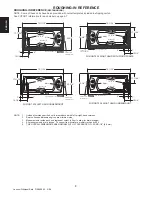
Page 6: ...alled BN60000 Heater Factory Installed BN60000 Heater FUZION 7260 WITH TEAK SINGLE MOTOR LH RH 72 1829 mm L 60 1524 mm W 22 3 4 578 mm H 16 3 4 425 mm A 12 1 16 306 mm B 274 lb 125 kg Factory Installe...

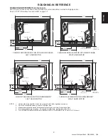
Page 7: ...11 SPECIFICATIONS Corner Heater Motor L H W 159 mm 6 1 4 SIDE VIEW END VIEW FUZION 6666 WITH WOOD FRAME Heater Motor L H W 127 mm 5 SIDE VIEW END VIEW FUZION 6666 UNDERMOUNT DRAIN OVERFLOW B A B A Und...

Page 8: ...Access Opt Service Access 17 11 16 2 7 10 1 4 12 x 4 Heater S 70 11 16 35 3 8 70 11 16 Motor 12 H x 18 L Service Access Opt Service Access 35 3 8 17 11 16 2 7 10 1 4 12 x 4 Heater S FUZION 7236 RIGHT...

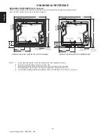
Page 9: ...hes To convert to millimeters multiply inches by 25 4 5 THE OVERALL DIMENSIONS ARE NOMINAL WITH A TOLERANCE OF 0 AND 1 4 6 4 mm FUZION 7260 SINGLE MOTOR UNDERMOUNT LEFT HAND MOTOR Motor Heater S 72 60...

Page 10: ...represent cutout in floor to allow for drain overflow 4 All measurements are in inches To convert to millimeters multiply inches by 25 4 5 THE OVERALL DIMENSIONS ARE NOMINAL WITH A TOLERANCE OF 0 AND...

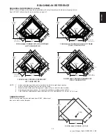
Page 11: ...0 AND 1 4 6 4 mm Motor 12 H x 18 L Service Access Heater S 46 61 66 20 X 4 32 97 Ref 66 37 23 9 29 32 97 40 94 40 94 69 68 FUZION 6666 CORNER WITH WOOD FRAME LEFT HAND MOTOR Motor 12 H x 18 L Service...

Page 12: ...hould be level to each other NOTE Drop In Bath units are equipped with metal anchor straps These straps can be used to secure the unit to the floor or sub floor to reduce movement after installation I...

Page 13: ...TAR MORTAR MUST BE IN CONTACT WITH ALL FOAM FEET With bath and template in this position using a grease pencil mark on the bath the center line positions through the cut out Remove template Measure fr...

Page 14: ...bath rim If maintenance or remodelling is required the counter may have to be removed Adhesive will permanently bond the counter to the bath This will make removal difficult and costly and may cause...

Page 15: ...tice is not commonly implemented it is an acceptable method In some cases access may have been provided in Area A but service is required in Area B which requires the unit to be pulled for service and...

Page 16: ...e 120 VAC 20 AMP pump motor or control box power cord ONLY to the 120 VAC 20 AMP GFCI circuit Connect the 120 VAC 15 AMP heater power cord ONLY to the 120 VAC 15 AMP GFCI circuit FOR 230 VAC units Con...

Page 17: ...ate the acrylic surface will require refinishing Ask your Jacuzzi Whirlpool Bath dealer for special instructions or visit our web site at http www jacuzzi com To find service agent listings for Electr...

Page 18: ...cular motion around the bath causing a total whirlpool effect Water Force The high volume fully adjustable jets can be adjusted to control the force of the water coming into the bath For robust action...

Page 19: ...om no air to maximum air Left Air Valve Status LED The Left Air Valve Status LED will show four LED lights at maximum air and only one LED light when the air is turned OFF Each additional LED indicate...

Page 20: ...heater includes an exclusive High Limit switch This safety circuit will not false trip from hot tap water It will only turn off the heater if the thermostat fails To reset press the button If the high...

Page 21: ...irlpool bath be purged at least twice a month For best results however we recommend that you purge your whirlpool bath after each use using our exclusive two part plumbing system cleaner made specific...

Page 22: ...ways be in place on the suction fitting to mini mize the potential hazard of hair and body entrapment NOTCH GASKET COVER STRAINER SCREW SUCTION FITTING SUCTION COVER STRAINER ASSEMBLY Chromotherapy Li...

Page 23: ...e properly connected Replace Control Panel and or Control Box Open jets by rotate counterclockwise With motor turned off remove safety cover and remove any debris Re place suction cover before operat...

Page 24: ...label is located on the wall of the bath near the pump motor Non jetted baths The label is located next to the overflow MODEL XXXXXXX NAME XXXXX COLOR XXXXX MFG XXXXX SER XXXXXX MADE IN USA THIS PRODU...

Page 25: ...ch as lightning floods earthquakes etc In addition THE COMPANY WILL NOT BE RESPONSIBLE FOR INCIDENTAL OR CONSEQUENTIAL DAMAGES or losses arising from any cause e g water damage to carpet ceiling loss...

Page 26: ...rum Dr Suite 400 Dallas TX 75254 Call 800 288 4002 To obtain warranty replacement for factory installed components for Company supplied options and accessories manufactured and supplied by the Company...

Reviews: