


14
07610-001-76-22-N
INSTALLATION
INSTRUCTIONS
The plumber MUST flush
the incoming water line!
DRAIN LINE
All plumbing connections must adhere to local, state, territorial, and national codes. The
installing plumber is responsible for ensuring the incoming water lines are flushed of debris
before connecting the machine. Chips and materials from cutting processes can become
lodged in the solenoid valves and prevent them from opening or closing. Any valves that
are found to be fouled or defective because of foreign matter left in the water line—and
any subsequent water damage—are not the responsibility of the manufacturer.
If water hardness tests greater than 3 GPG, install the Scaltrol Water Treatment system
(see the Plumbing Options page) into the water line before the machine’s incoming
water connection point. If water hardness tests 3 GPG or lower, install the water supply
line directly to the machine’s incoming water connection point. Iron in the water line
can cause staining. A filter designed to remove iron from the water supply is highly
recommended for supplies in excess of 0.1 ppm.
The machine
uses a flow pressure of 20 ± 5 PSI for the incoming water line. Do not
confuse static pressure with flow pressure. Static pressure occurs when there is no flow
and the valves are closed. Flow pressure occurs when water is running into the machine.
The water supply line must be 3/4" NPT minimum and must be able to provide water at t
he
minimum temperature indicated on the machine data plate.
A shut-off valve
(
not supplied
) should be installed to isolate the machine from the water
system in the event service is required. An optional shock absorber (
not supplied
) should
also be installed on the incoming water line (see the Plumbing Options page). This
prevents water hammer (hydraulic shock) from causing damage to the equipment.
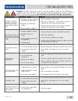
The drain for the machine is a gravity-discharge drain. All piping to the machine drain must
be a minimum 1 1/2” NPT and must not be reduced. There must be a minimum 1 1/2" air-
gap between the machine drain line and the floor drain or sink. The floor drain or sink must
be a minimum 3" NPT. If a grease trap is required by code, it should have a flow capacity
of 30 GPM. AJ-44 machines have one drain connection point and AJ-66/80 machines
have two (connected and drained into one facility floor drain or sink).
PLUMBING
i
A water hardness test
MUST be performed.
Machine
Drain Line
1 1/2” [38 mm]
MIN, Must NOT
Be Reduced.
Pitch 1/4” per ft.
Must Install Machine
Drain Line above
3” [76 mm] MIN
Floor Drain or Sink
1 1/2”
[38 mm]
MIN
Air-gap
Drain
Connection
1 1/2
[38 mm]
!
CAUTION
CAUTION! An air-gap
is required between the
drain line and floor drain
or sink.
Summary of Contents for AJ-44
Page 72: ...64 07610 001 76 22 N PARTS AJ 66 RACK RAILS Left to Right Right to Left 1 4 2 3 4 5 6 7 1 ...
Page 84: ...76 07610 001 76 22 N SCHEMATICS AJ 44CGP 208 230 V 60 HZ 1 PHASE AJ 44CGP SCHEMATIC ...
Page 85: ...07610 001 76 22 N 77 SCHEMATICS AJ 44CGP 208 230 V 60 HZ 3 PHASE AJ 44CGP SCHEMATIC ...
Page 86: ...78 07610 001 76 22 N SCHEMATICS AJ 44CGP 460 V 60 HZ 3 PHASE AJ 44CGP SCHEMATIC ...
Page 87: ...07610 001 76 22 N 79 SCHEMATICS AJ 66CGP 208 230 V 60 HZ 1 PHASE AJ 66CGP SCHEMATIC ...
Page 88: ...80 07610 001 76 22 N SCHEMATICS AJ 66CGP 208 230 V 60 HZ 3 PHASE AJ 66CGP SCHEMATIC ...
Page 89: ...07610 001 76 22 N 81 SCHEMATICS AJ 66CGP 380 460 600 V 60 HZ 3 PHASE AJ 66CGP SCHEMATIC ...


