


07610-002-41-09-F
2
1 13/16”
5 1/4”
14 7/8”
TO THE
WALL
13”
9”
1 13/16”
B
E
F
A
16 1/2”
27 1/2” (AB ONLY)
TOP VIEW
FRONT VIEW
35 1/2” (APRB ONLY)
16 1/2”
21”
18”
19’’
22 1/4”
20 1/4”
10U
29 1/4”
5” HH
19 1/4”
15 1/4”
10U
24 1/4”
5” HH
2 3/4”
C
CIRCUIT
BREAKER
B
A
E
4”
20”
14 1/2”
11”
G
D
34”
25”
10U ONLY
20 1/2”
25”
10U ONLY
14” TO
INLET
5”
10U ONLY
A
B
F
5 1/2”
LEFT VIEW
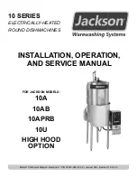
LEGEND
A - Water inlet 1/2” NPT. Plumbing can be directed
either left or right.
B - Drain connection 1 1/2” NPT
C - Electrical connection
D - Clearance for dishes:
10” (10U/10AB/10APRB 4” shorter hood)
14” (10A/10AB/10APRB standard hood)
19” (10A/10AB/10APRB 5” higher hood)
E - Power rinse pump motor (10APRB only)
F - Booster tank (10AB/10APRB/10U only)
G - Machine height:
45 1/2” (10U/10AB/10APRB, 9” shorter leg, 4” shorter hood)
58 1/4” (10AB/10APRB standard leg and hood)
63 1/4” (10AB/10APRB, standard leg, 5” higher hood)
All dimensions in inches.
All vertical dimensions are +/- 1/2” from the
fl
oor
due to the adjustable bullet feet.
SPECIFICATIONS
10AB/10APRB/10U MACHINE DIMENSIONS