SERVICE PROCEDURES continued
Steps:
(1)
DISCONNECT THE ELECTRICAL POWER TO THE DISHWASHER AT THE MAIN
CIRCUIT BREAKER BOX WHEN SERVICING. PLACE A TAG ON THE CIRCUIT
BOX INDICATING THE CIRCUIT IS BEING REPAIRED.
(2)
Disconnect power and conduit from dishwasher terminal block.
(3)
Turn off the water supply and disconnect the water supply line.
(4)
Disconnect the dishwasher drain hose from the kitchen's drain. Drain machine of any
water at this time.
(5)
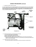
Move machine out and lay machine onto its back.
(6)
Remove pump hose to drain valve.
(7)
Remove pump hose from suction port.
(8)
Remove pump hose from discharge port.
(9)
Remove drain valve mounting bracket from motor bracket.
(10)
Remove the pump motor assembly by loosening the (4) locknuts securing the motor
mounting bracket. Note: Mounting bracket is slotted to allow easy removal and
installation. Remove (2) of the locknuts on one side and slide assembly toward that
side and remove. Once the assembly is removed, disconnect wire leads from motor
wiring box.
(11)
Install replacement motor in reverse order of above.
(12)
Check motor wiring as follows:
Low Voltage Wiring: (115V)
Brown & Red wires on terminal #2
Blue wire on terminal #4
Empty on terminal #6
L1 on terminal #4
L2 on terminal #1
High-Voltage Wiring: (230V)
Blue & Red wires on terminal #2
Brown wire on terminal #6
L1 on terminal #4
L2 on terminal #1
C. To replace pump shaft seal.
The pump motor assembly recirculates the wash sump water through the wash spray arms during the wash
cycle. It also drains the wash water during the drain cycle when the motor operated drain valve is opened.
The pump motor is mounted under machine behind electrical control panel. To replace pump motor or
pump seal, impeller, gasket, it is necessary to completely disconnect dishwasher from power, water and
drain. Machine must be laid down on it's side or back for removal of pump motor assembly.
The pump is part of the total motor-pump system and utilizes one shaft seal and ceramic to prevent the
pump from leaking around the impeller and shaft.
Steps:
(1)
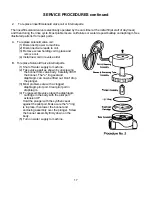
Follow procedures (1-10) above and remove pump casing.
(2)
Remove Impeller by holding shaft at opposite end of impeller
with a screw driver.
Unscrew impeller in counterclockwise direction.
Summary of Contents for JP-24B
Page 5: ...PARTS ID FUNCTION 3 ...
Page 6: ...PARTS ID FUNCTION 4 ...
Page 7: ...PARTS ID FUNCTION 5 ...
Page 30: ...SERVICE PROCEDURES continued ...
Page 62: ......
Page 63: ......
Page 64: ......


