Plasma 33 H
Operating Manual
Page 9
9. Functional description of the control PCB
1
2
5V
BT OK
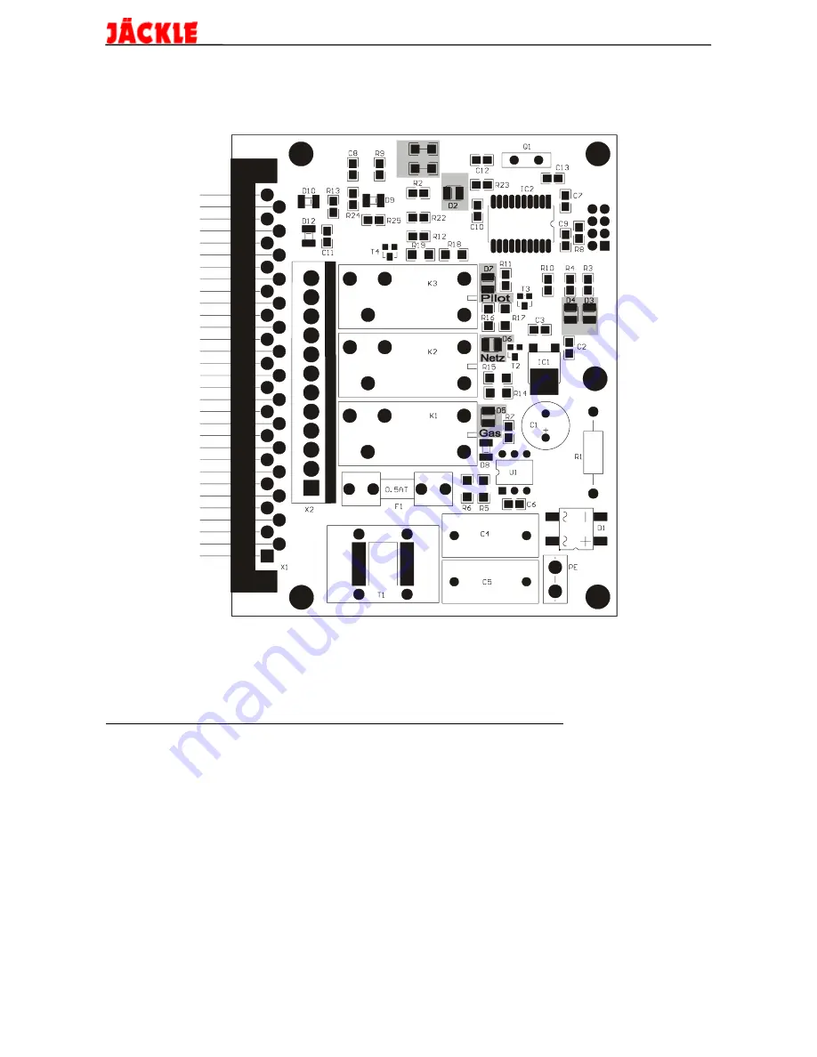
Picture 9.1 View on the PCB PL 3
The components in the grey fields have the following functions:
The LED D2 ‚5V‘ indicates the correct voltage on the PCB.
The LED D3 ‚OK‘ shows the normal function of the microprocessor.
The LED D4 ‚BT‘ shows the function of the torch trigger and the possible errors. They
are described in the next chapter ‘error messages’.
The LED’s D5 ‚Gas‘‚ D6 ‚Netz‘ and, D7 ‚Pilot‘ are illuminated, when the relay next to
the led is switched on by the microprocessor.


