background image

39 

8.


设定选购项


PERFORMING OPTIONAL SETTING 

(1)


选购项设定的变更方法


Changing procedure of  the  optional setting 


1)


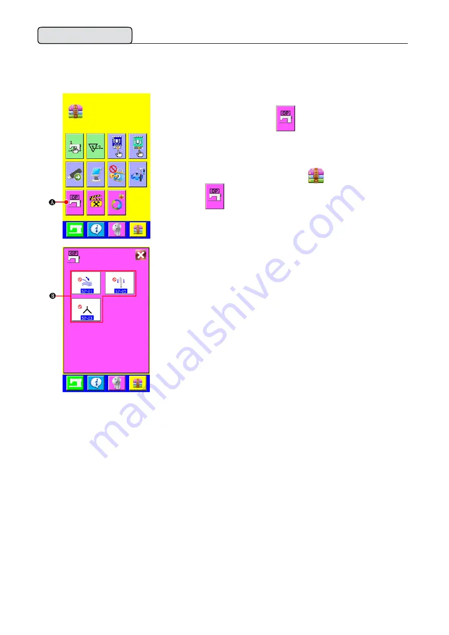
显示设定选购项一览画面


在画面上按设定选购项按钮

A 之后,设定选购项一览画面

(画面A)被显示出来。 


Displaying the optional setting list screen


Pressing MODE CHANGEOVER key  

 , OPTIONAL SETTING 

button


A


is  displayed on the screen.


Press this button and the optional setting list screen (screen A) is 
displayed.


设定选购项一览画面

(

画面

A) 

Optional setting list screen (screen A)


2)


选择想变更的选购项设定


请选择想变更的数据项目按钮

B 。 


Selecting the  option setting you  want  to  change


Select DATA ITEM button 

B

 you want to change.


Summary of Contents for JK-T5878-58G

Page 1: ...LUBRICATING THE OIL TANK 7 V 8 PREPARATION OF THE SEWING MACHINE 8 1 8 HOW TO OPERATE THE SEWING MACHINE HEAD 8 1 8 Thread used 8 2 8 How to pass the needle thread 8 2 9 HOW TO WIND THE BOBBINS 9 1 9...

Page 2: ...23 2 24 Performing the new creation of pattern 24 3 25 Copying the pattern 25 4 27 Erasing the pattern 27 6 28 CHANGING THE SEWING DATA 28 1 28 Changing procedure of the sewing data 28 2 29 Sewing da...

Page 3: ...a folder 54 3 54 Performingcommunication by using the media 54 4 55 Take in of the data 55 14 56 UPDATING PROGRAM OF OPERATION PANEL 56 15 56 SYSTEM SETUP 56 16 57 LOCK COPY AND NEW FUCTION 57 17 57 P...

Page 4: ...e indicates the designated air pressure of 0 6 MPa This is necessary particularly when the compressor is stopped for a lunch break or the like If the compressed air pressure is equal to or less than t...

Page 5: ...unit 3 Operation panel 4 Sewing machine head 5 Marking light 6 Pcs box 7 Main power switch 8 Foot pedal 9 Stacker unit 10 Clamp foot With this machine consisting of the aforementioned 10 units you ca...

Page 6: ...h standard 3 stitches 5 Needles DB 1 11 6 Sewing width 1 50mm 7 Sewing length 15 300mm 8 Thread Spun thread 60 Recommended 9 Cloth feed mechanism Driven by servo motor 10 Control By a micro computer 1...

Page 7: ...er and fix foot pads 1 4 places and raise casters 1 after moving the machine to the level and stabilized place CAUTION Take out operational panel from accessory case and then connect the line Remove t...

Page 8: ...terials that have fixed the stacker and then remove the screw 2 Adjust the stack position 3 As shown in the fig 1 2 lock the whole stacker with screw and plate Clamp bar stacker is delivered in the st...

Page 9: ...igure above cut and remove the packing material that has fixed the installing operation panel on frame To prevent malfunction due to static electricity install operation panel on the panel base to use...

Page 10: ...se according to the screen display Oil should not be too much or too little be careful 1 To prevent accidents caused by abrupt start of the sewing machine do not connect the power plug until lubricati...

Page 11: ...n A displayed Then pass needle thread in the order as shown in the figure below After that press the button and the nose and the small press foot will be homing Turn OFF the power before starting the...

Page 12: ...shaft 2 Wind the thread several times around the bobbin 1 in the direction indicated by the arrow Check that the thread is not loose anywhere along the thread path Push the bobbin presser arm 3 toward...

Page 13: ...urn automatically Then press the botton B to stop and remove the bobbin cut the thread with the knife 4 1 2 80 5 6 3 6 1 To ensure the appropriate remaining amount of bobbin thread it is important to...

Page 14: ...s together with the bobbins When fitting fit the bobbin cases into the hook driving shaft and tiltlevers 1 5 HOW TO ADJUST THE THREAD TENSION Adjusting bobbin thread tension Turn bobbin thread tension...

Page 15: ...of the data input screen and the information screen is performed 4 COMMUNICATION key Change over of the data input screen and the communication screen is performed 5 MODE CHANGEOVER key Change over o...

Page 16: ...een is closed In case of the data change screen the data during changing can be cancelled ENTER botton Data changed are determined UP SCROLL botton This button scrolls button or display upward DOWN SC...

Page 17: ...purchase pattern Nos 1 to 11 have been registered Change the sewing data in accordance with the sewing types for use The number to which the pattern has not been registered is not displayed B Sewing...

Page 18: ...temporary stop switch D is pressed during sewing the device can be stopped At this time the error screenis displayed to inform that stop switch is pressed When RESET button E is pressed the error is r...

Page 19: ...16 2 EXPLANATION OF THE BASIC SCREEN A B C D E F G No No H I J K L M N 9...

Page 20: ...layed and the pattern data can be selected G PATTERN NO LIST button Pattern No list screen is displayed and the pattern data can be selected H THREADING LIGHT button Click the button the threading lig...

Page 21: ...screen screen A is displayed A Counter setting screen screenA 2 2 A B B Select the kind of counter There are two kinds of counters with this sewing machine number of pcs counter and bobbin thread rem...

Page 22: ...input the existing value of counter Number of pcs counter UP counter Every time one piece sewing is performed the existing value is counter up When the existing value is equal to the set value the cou...

Page 23: ...0 Here input the target value of counter When 0 is inputted to the target value of counter only the target value is displayed during sewing and the count up screen is not displayed 2 Releasing procedu...

Page 24: ...bin thread remaining amout adjustment counter setting pop up screen screen B is displayed Then the bobbin thread remaining amount adjustment counter motion ON OFF can be set B Bobbin thread remaining...

Page 25: ...ion count up 0 A When the bobbin thread remaining amount counter value becomes 0 at the sewing end the count up screen is displayed and the buzzer sounds Replace the bobbin thread of the bobbin When C...

Page 26: ...ayed the selection of pattern can be selected Call the pattern list screen Press PATTERN LIST button A and the pattern list screen is displayed 3 B Select the pattern Press patterndata you desire to s...

Page 27: ...EATION button A and the pattern new creation screen is displayed 3 No B No C D No 4 No E No Input the pattern No Input pattern NO you desire to newly create with the keys to B It is possible to retrie...

Page 28: ...after erasing the pattern once For the erasing procedure see VI 5 4 Erasing the pattern 1 2 No A Display the input screen When the input screen is displayed it is possible to copy Call the pattern No...

Page 29: ...F Input the pattern No of copy destination Input the pattern No of copy destination with ten keys or D It is possible to retrieve the patern No which has not been used yet with buttons E and F No B Co...

Page 30: ...n A 3 B C Select the pattern to be erased Select the pattern to be erased from pattern list button B Next press ERASE button C and the pattern erase confirmation screen is displayed 4 A 1 Determine th...

Page 31: ...d can be registered to SEWING DATA SHORTCUT button B in the input screen and be set directly In addition the detailed sewing data can be set by pressing A A Sewing data list screen screen A 2 A A Sele...

Page 32: ...29 2 1 No S09 50mm S10 0 30mm S09 20mm S10 5mm...

Page 33: ...ack tack at sewing start is selected Condensation Back tack Selection of condensation back tack at sewing end Selection of condensation back tack at sewing end is performed Condensation Back tack Sele...

Page 34: ...31 2 No 1 0 3 4 0 1mm 2 5mm 3 30 1 5 1 0 1 5 0 1mm 1 0mm 1 30 1 3 1 0 3 0 0 1mm 2 0mm 3 30 1 5 1 0 1 5 0 1mm 1 0mm...

Page 35: ...32 No 1 30 1 3 1 0 3 0 0 1mm 2 0mm 0 5 2 5 1mm 2 0mm 10 200 1mm 90mm 200 200 1mm 0mm 1900 4000 350rpm 3300rpm 500 1550 350rpm 500rpm...

Page 36: ...ng start is set It is possible to set only when is set to selection of back tack 1 30 1stitch 3stitch Back tack pitch at sewing start Back tack sewing pitch at sewing start is set It is possible to se...

Page 37: ...0 1mm 90mm Stacker position setting After complete sewing big foot move to the designated spot and stacker action 200 200 1mm 0mm Sewing speed under the high speed mode Number of revolutions at lockst...

Page 38: ...Press MODE CHANGE OVER key and the memory switch button A is displayed When this button is pressed the memory switch data list screen A is displayed A Memory switch data list screen screen A 2 C B Sel...

Page 39: ...36 2 No 1 50mm 1mm 15mm 3 9 1 5 3 9 1 5 30 99 1 60 10 100 1 40 1 0 0 9 9 0 1S 0 5S 2 0 0 9 9 0 1S 0 8S...

Page 40: ...ing is set 3 9 1 5 Return speed of clamp foot The speed of clamp foot returned to the backward setpoint is set 3 9 1 5 The speed of center knife The speed of center knife is set 30 99 1 60 Falling tim...

Page 41: ...amne time A Thread breakage alarm screen screenA 1 A B 2 C A D A Press backward key A and the presser returns stitch by stitch Press forward key B and the presser advances stitch by stitch and with th...

Page 42: ...ing list screen Pressing MODE CHANGEOVER key OPTIONAL SETTING button A is displayed on the screen Press this button and the optional setting list screen screen A is displayed A Optional setting list s...

Page 43: ...erform the respective optional operations No Item Setting range Edit unit Initial value Clamp bar stacker mounting not mounting is set Not mounting Mounting Alignment unit mounting not mounting is set...

Page 44: ...ect the conditions of buttons Every time the buttons from B to J are pressed display non display of the buttons can be changed over Customize and use the buttons in accordance with the customers using...

Page 45: ...g screen displayed 2 B H Set the conditions of buttons Every time the buttons from B to H are pressed button display non display can be changed over Customize and use the buttons in accordance with th...

Page 46: ...ntainer so users need to enter a password to access and you can get the password from manufacturer A Test screen screen A 2 B IO1 IO2 IO3 IO4 IO5 IO6 Select the IO port button you want to test in the...

Page 47: ...est button and the sewing machine head test screen screen B is displayed Press button D and set whether to actuate middle knife action or not Display Description To actuate Not to actuate Press up dow...

Page 48: ...t down the center knife or not Display Description To put down the center knife Not to put down the center knife Press up down button I to adjust the motor speed of center knife Press START KEY J to s...

Page 49: ...test Display Description To actuate Not to actuate 7 IO5 M JN34 IO5 input port test Select the input port sensor button M you want to test The test port number is JN34 as at left Display Description S...

Page 50: ...port list A Input test screen screen A B Output test screen screen B A A Press button A in the input test screen and then input list will displayed B A Press button A in the output test screen and th...

Page 51: ...n needle and needle plate detection JN25 Clamp foot forward movement detection JN26 Clamp foot backward movement detection JN27 Center knife position detection JN28 Initial point of machine head detec...

Page 52: ...rner knife EC05 Blow cylinder EC06 Middle presser of alignment unit EC07 Left presser of alignment unit EC08 Right presser of alignment unit EC09 Assist stacker feed cylinder up and down EC10 Assist s...

Page 53: ...layed A Information screen screen A B C D E F B Maintenance inspection information Oil replacement grease up time needle replacement time cleaning time etc are specified and when the specified time ha...

Page 54: ...nformation screen 3 Three items of the information below are displayed in the maintenance inspection information screen Needle replacement Cleaning time Oil replacement time 2 B C Clear the replacemen...

Page 55: ...reen screenA is displayed A Date Time adjustment screen screenA 2 Modify date time Click the information you want to modify Press ok key to save the alteration and Press the cancel button cancel the r...

Page 56: ...number of pieces C This item automatically displays the operation time D This item automatically displays the program version number 4 Control structure diagram A A Display the control structure diagr...

Page 57: ...f data Sewing data BIN Sewing data created by the sewing machine exclusive 2 The structure of the media folder 3 Performing communication by using the media 1 Uncover the black rubber cover 1 and inse...

Page 58: ...ommunication screen screen A is displayed Select the communication method There are two communication method as described below A Writing data from USB to operation panel B Writing data from operation...

Page 59: ...utton A is displayed on the screen When this button is pressed the screen of updating program by USB is displayed 15 SYSTEM SETUP Changing the system Settings A System setup screen screenA A A Press M...

Page 60: ...Press this button you can set lock or unlock The copyand new fuction button of the sewing screen will convert to type B in the lock state Display Description Unlock Lock 17 PARAMETER INITIALIZATION A...

Page 61: ...pection related to the sewing machine When dust adheres to the small places of the machine such as clamp foot or the like normal operation is disturbed Be sure to perform cleaning before the work In a...

Page 62: ...ing screen is displayed Then the ON OFF of marking light is set WARNING 1 If the laser light directly enters the eye eyesight trouble may be caused Do not look into the laser inlet outlet 2 Never perf...

Page 63: ...screen of maintenance video is displayed A Maintenance screen screen A 2 B V01 V02 V03 V04 V05 V06 V07 U 2 Select the video you want to play in the selection area B Press the button to enter the playe...

Page 64: ...dcast Press again video pause Rewind button Each click video back 10s Fast forward button Each click video fast forward 10s Stop button After press this button the video stopped and then press the pla...

Page 65: ...62 4 E01 E02 E03 E04 E05 E06 U U U E07 E08 E09 E10...

Page 66: ...63 E12 E13 1 2 E14 E15 E16 E17 E18 E21 E22 E23...

Page 67: ...64 E24 E43 No E45 No E46 No E64 0 1 2 E66...

Page 68: ...which control the movement of machine head then press reset key E05 Sewing head right point sensor error Sewing head is not in the right position Please check the sensor and signal cable of servo moto...

Page 69: ...ight clamp foot and the sewing head may take place the collision The current set of sewing width greater than the distance of two clamp foot Need to adjust the mechanical position or Modify sewing wid...

Page 70: ...tered Possible to recover with CANCEL button E45 New creation disapproved When the registered pattern is selected to the new creation pattern No Possible to recover with CANCEL button E46 Data of desi...

Reviews: