background image


3

 / 

8


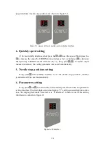
upper and lower needle stop positions are shown in Figure 3-1. 


Figure 3-1 upper and lower needle position display interface 

4.


Quickly speed setting 

In the standby interface, short press the

or to set the speed. Short press the

to increase the speed by 100RPM (value increases by 1), short press

to decrease 

the  speed  by  100RPM  (value  decreases  by  1),  long  press

( )  to  realize  rapid 

increase (decrease), the setting parameters are saved automatically. 

5.


Needle stop positions setting 

Long  press

in  the  standby  interface  to  set  the  needle  stop  positions,  and  the 

parameters will be saved automatically. 

6.


Parameters setting 

Long press

and (for around 3S) in the standby interfaceto enter the parameter 

setting interface. The first digit nixie tube displays "F" and the second digit nixie tube 
does not display (hereinafter referred to as "F interface", which is one of the setting 
interfaces), as shown in figure 6-1. 


Figure 6-1 F interface 

Summary of Contents for F5

Page 1: ...ring The grounding wire of the power line must be firmly and effectively connected with the earth All spare parts for maintenance shall be provided or approved by the company before use Before carryin...

Page 2: ...d The grounding wire of the system is yellow green wire which must be reliably connected to the safety protection grounding of the power grid to ensure safe use and prevent abnormal conditions Note al...

Page 3: ...to realize rapid increase decrease the setting parameters are saved automatically 5 Needle stop positions setting Long press in the standby interface to set the needle stop positions and the paramete...

Page 4: ...ewing computer model If you want to modify the parameters you can press to change the parameter value to 1 as shown in Fig 6 3 corresponding to ZB simple type and then short press to save After oK is...

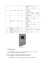
Page 5: ...trol box 0 Off 26 132VAC 27 137VAC 28 142VAC 29 147VAC 30 152VAC 31 157VAC A Ridge crossing assistance 0 1 1 0 Off 1 On b Speed controller model selection 0 1 0 0 Computerized type 1 ZB simple type U...

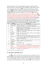
Page 6: ...played number 100 actual speed J2 Power Display the real time power in standby and running states and the displayed number 10 actual power J3 Voltage Display the input voltage in standby mode and the...

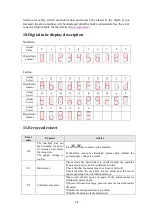
Page 7: ...been running for about 30 minutes and enters the sleep state The supply voltage is too low Press or key to wake up the machine If the alarm cannot be eliminated please check whether the power supply...

Page 8: ...turned on this alarm will appear when the machine head dumps Turn off the safety switch or restore the head position If the alarm cannot be eliminated please contact the maintenance personnel EA Soft...

Reviews: