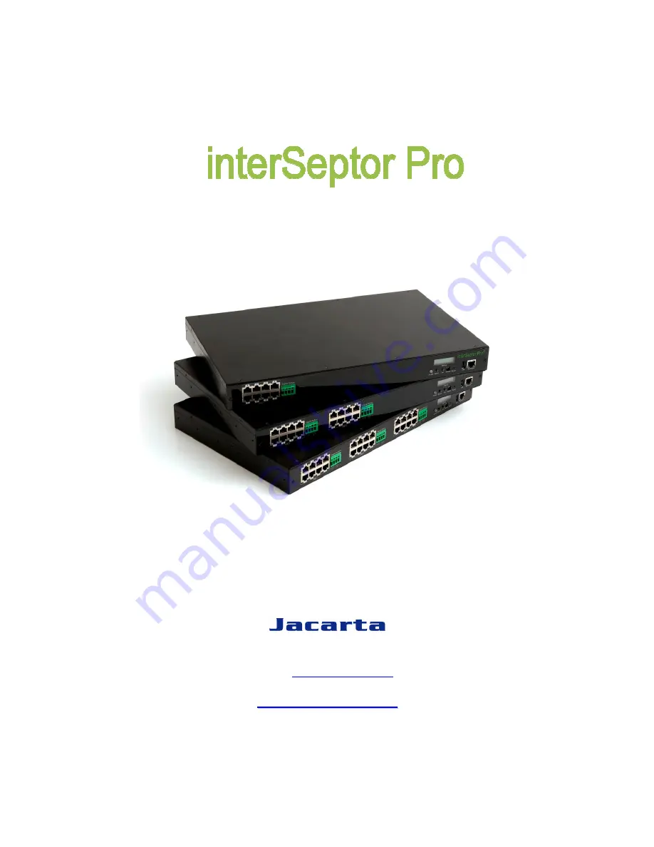
background image


E

E

n

n

v

v

i

i

r

r

o

o

n

n

m

m

e

e

n

n

t

t

a

a

l

l


M

M

o

o

n

n

i

i

t

t

o

o

r

r

i

i

n

n

g

g


S

S

y

y

s

s

t

t

e

e

m

m


f

f

o

o

r

r


D

D

a

a

t

t

a

a


C

C

e

e

n

n

t

t

e

e

r

r

s

s

,

,


S

S

e

e

r

r

v

v

e

e

r

r


R

R

o

o

o

o

m

m

s

s

,

,


R

R

a

a

c

c

k

k

s

s


8-Port, 16-Port, 24-Port Versions 

User Manual 

V1.1


T. +44 (0) 1672 511125 


Email: 

[email protected]


w

w

w

w

w

w

.

.

j

j

a

a

c

c

a

a

r

r

t

t

a

a

.

.

c

c

o

o

.

.

u

u

k

k


Summary of Contents for InterSeptor Pro

Page 1: ...n ng g S Sy ys st te em m f fo or r D Da at ta a C Ce en nt te er rs s S Se er rv ve er r R Ro oo om ms s R Ra ac ck ks s 8 Port 16 Port 24 Port Versions User Manual V1 1 T 44 0 1672 511125 Email supp...

Page 2: ...ment This device complies with the CISPR Class B standard EN 55024 1998 Electromagnetic compatibility Generic immunity standard Part1 Residential and light industry RoHS This device is RoHS compliant...

Page 3: ...14 3 3 Device Management 15 3 3 1 Device Board Screens 15 3 3 2 Schedule of Device Board Screens 17 3 4 System Configuration 18 3 4 1 Date and Time 19 3 4 2 System Configuration 19 3 4 3 System Contro...

Page 4: ...2 7 Parameter Group Configuration 37 6 2 8 EMD Configuration 38 6 2 9 EMD of Device Board Monitoring 38 6 2 10 Digital Output control 39 6 2 11 Access Control Table Configuration 39 6 2 12 Trap Recei...

Page 5: ...interSeptor Pro 5...

Page 6: ...ed You can set the interSeptor Pro settings from any SNMP management station or by web browser using HTTP forms and objects E mail notification Supports e mail notification through SMTP via e mail cli...

Page 7: ...U type handles x 2 U type handle screws x 4 Feet screws x 4 RJ45 to RJ45 male cable for EMD connection x 1 2 3 version dependant Accessory Pack containing cable tie velcro and screws for mounting EMD...

Page 8: ...n 8 1 3 Front View Figure 1 1 interSeptor Pro front view Note The USB 2 0 ports are standard interface connectors designed primarily for use with an external keyboard or keypad 1 4 Rear View Figure 1...

Page 9: ...other end to the RJ45 port on an EMD 5 Insert one end of the power connector to the AC In socket on the rear of the interSeptor Pro Connect the other end to a power socket Upon successful connection...

Page 10: ...on to enter operation mode You can perform system configuration through the menus available in operation mode Press the Down button to scroll through the settings menus Press the Set button to enter s...

Page 11: ...Administrator button at the bottom of the page Enter the default login name iSPro and password admin The login name and password are case sensitive 2 Click the System Configuration menu then do the fo...

Page 12: ...gure 3 2 Device Monitoring Comprehensive View 3 2 1 Comprehensive View This page displays the information of all the sensors and output devices connected to the interSeptor Pro It also provides an ove...

Page 13: ...vice Board 1 2 and 3 Web Pages provide detailed information for all sensors or output devices connected to each device board The parameters are updated automatically every 5 seconds Note The following...

Page 14: ...3 5 Identification Web Page 3 2 4 Alarm Table Web Pages This page provides information on the number of currently active alarms alarm ID alarm time and alarm description All the information in this p...

Page 15: ...chedule of Device Board 1 Device Board 2 Schedule of Device Board 2 Device Board 3 Schedule of Device Board 3 Figure 3 7 Device Management Device Board 1 3 3 1 Device Board Screens The Device Board 1...

Page 16: ...te when the value reaches 20 but will not deactivate until the value reaches 23 For the contact alarm sensors the hysteresis can be used to adjust the sensitivity of an alarm The alarm will be active...

Page 17: ...can be postponed if necessary If set to zero the digital output will be activated as soon as an alarm is triggered Extend Enter a value in seconds before which the digital output changes back to star...

Page 18: ...nly alarm types that are not selected will alarm if triggered Click Set Value to confirm and save the schedule The configured schedule will appear on the page Click the Edit button to edit the schedul...

Page 19: ...ate and time of the interSeptor Pro manually or synchronize the settings with the computer time or an NTP Network Time Protocol server Figure 3 11 Date and Time 3 4 2 System Configuration This page al...

Page 20: ...cation protocol You can also click the Reset to Default button to reset all default configurations for the interSeptor Pro or the restart interSeptor Pro button to restart the interSeptor Pro Figure 3...

Page 21: ...gement Figure 3 15 Trap receivers 3 4 6 Email Notification This page allows you as administrator to configure the mail server and mail receiver settings to send alert emails when an event occurs After...

Page 22: ...he GSM modem function to ENABLE Figure 3 18 SMS configuration page Configure the following settings to enable disable the GSM modem GSM Modem Function Choose Enable Disable to enable or disable the GS...

Page 23: ...Severe to set the minimum level of the event to be received Action Choose Enable Disable to enable disable sending the message to the SMS recipient Body Enter the content of the SMS Prefix Enter the t...

Page 24: ...al links setup Figure 3 22 the links appear on the left of the page 3 4 9 SSL Root CA Configuration You can download the Root CA certificate of the interSeptor Pro and the Root CA certificate of the i...

Page 25: ...ice 2 Events History Log of Device 3 Device 3 Events Extended Log of Device 1 System Events Extended Log of Device 2 Clear Save Log Extended Log of Device 3 3 5 1 History Logs of Devices These pages g...

Page 26: ...ards The minimum maximum and the average values of temperature and humidity are shown Note The administrator can change the consolidation interval by changing the value of the Extended Log Interval in...

Page 27: ...he maximum number of entries rows is reached Figure 3 29 Device 2 Events Log Index page Figure 3 30 Events Log Data of Device 1 3 5 4 System Events This page lists all the system events The administra...

Page 28: ...5 5 Clear Save To save the interSeptor Pro log data to a file in Microsoft Excel format click the links under the Save Log Data section You can also clear the log data in this page Figure 3 33 Clear a...

Page 29: ...4 1 Java Monitor page Function Icons Display switch Two display styles gauge or overall chart presentation can be selected This icon is used to switch the display of the device parameters from gauge...

Page 30: ...ph You can select any combination of the parameters to be displayed by checking the check box next to each parameter on the monitor screen Click the Refresh button at the bottom of the page to apply t...

Page 31: ...en Click the Refresh button to apply the changes Figure 4 4 Extended History Log Monitor Minimum Display the minimum values of the temperature humidity or voltage of the EMDs sensors and the output de...

Page 32: ...et or the SNMP HTTP Access Control via web browser in the interSeptor Pro you can only view the interSeptor Pro status from SNMP and will not be able to perform any configuration on the interSeptor Pr...

Page 33: ...listed as Net Mask and Gateway in the system configuration menu 8 Configure any of the other system configurations you require see figure 2 1 LCD Screen Operation mode menus for details then select Ba...

Page 34: ...tion Description Example Remark 1 IP Address The interSeptor IP address 192 168 1 69 2 Gateway Address The network default gateway 192 168 1 254 3 Network Mask The sub net mask setting 255 255 255 0 A...

Page 35: ...ontrol settings menu 8 HTTP Control Opens the HTTP security control menu 9 SNMP Control Opens the SNMP control menu A LCD Security Enable or Disable LCD security This is disabled by default Disable B...

Page 36: ...fter completing these settings press 0 to return to the configuration menu NO Function Description Example 1 SSH Control Enable Disable the SSH Control Enabled 2 SSH Port Configuration Port for SSH co...

Page 37: ...management port to be used SNMP traps are not affected using this setting and always use UDP port 162 6 2 7 Parameter Group Configuration From the configuration menu press 3 to modify the SNMP identif...

Page 38: ...ich will give the current values of the Sensors connected to that Device Board See Figure 6 10 Figure 6 10 EMD Status Table No Function Description Example Remark 1 EMD status of Device Board 1 Access...

Page 39: ...eptor Pro access you can use the access table to add the IP addresses of the PC s on which you wish to modify the access permissions see Figure 6 12 Figure 6 12 Access Control table NOTE The configura...

Page 40: ...menu 6 2 14 End of interSeptor Pro Configuration When configuration is complete press 0 to terminate the console connection NOTE After completing all the settings press 0 to terminate the connection...

Page 41: ...ure Diagnostic Mode ON OFF Reserved OFF ON Reserved OFF OFF Operating Mode A2 EMD Cable Definition The cable for EMD ports of the InterSeptor Pro straight through CAT5 network cable RJ45 RJ45 Color 1...

Page 42: ...trator status and have the read write authority for the interSeptor Pro B2 Updating interSeptor Pro firmware via Upgrade exe 1 Open the upgrade exe from the upgrade folder on the CD provided with the...

Page 43: ...hen click the modify button enter the User name and Password of the interSeptor Pro to be upgraded Figure B 3 upgrade exe modify page 5 Then click the upgrade button click ok at the end of the upgrade...

Page 44: ...ome with the modem Set the desired baud rate with the following command at ipr 38400 press enter Then reconnect HyperTerminal using the new baud rate Now make the changes permanent with the following...

Reviews: