


JA-82K control panel installation manual
- 5 -
MKH51102
3.7
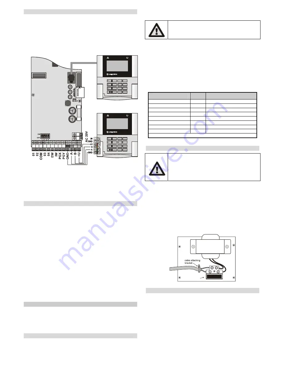
Wired keypad connection
The control panel can be operated and programmed by a JA-80E hard-
wired keypad. A screened four-cord flat cable connecting the corresponding
terminals should be used for permanent connection between the keypad and
the control panel (see fig. 7.)
The keypad can also be connected to a bus connector on the control
panel box using a flat cable (max 10 metres) with RJ connectors for the
purpose of servicing or system debugging.
1
2
3
ABC
4
5
6
A
7
8
9
ON
0
#
B
?
OFF
ESC
A
B
C
OASiS
1
2
3
ABC
4
5
6
A
7
8
9
ON
0
#
B
?
OFF
ESC
A
B
C
OASiS
Control and programming
keypad JA-81E
Modular connection
cable
fig. 7 Wired keypad connection
Note:
When you use the INP keypad hard-wired input to connect the door detector,
its reaction is always delayed (it triggers an entry delay) and it is assigned to
section C.
We recommend having only a single JA-80E hard-wired keypad in the
system.
3.8
Control panel resetting
If you need to set the factory-default settings in the control panel, perform the
following:
1. Disconnect the back-up battery and the mains (using the terminal
board fuse),
2.
Connect the RESET link
and leave it connected,
3.
Connect
the back-up battery and the
mains
,
4.
Wait
until the green LED starts flashing and then
disconnect the
RESET link.
If you need to reset the control panel with preset parameters according to EN
50131-3 (see 6.48) follow these next steps:
1. Disconnect the back-up battery and the mains (using the terminal
board fuse),
2.
Connect the RESET link
and leave it connected,
3.
Connect
the back-up battery and the
mains
,
4.
Wait
until the green LED starts flashing and
key in the sequence
8080
an finally
disconnect the RESET link.
Note:
After a RESET, all wireless devices and access cards are erased from the
control panel as well as user codes.
The Master code changes to 1234, and the service code to 8080.
If resetting is disabled (see 6.8)
it is impossible to reset the control panel.
4
Control panel power supply
Once the control panel is assembled and all modules are in place, you can
proceed with putting the control panel into operation. We recommend
switching the control panel on without any wired detectors connected, using
only the wired keypad (if it is used in the system) for the first time. Only then
should you continue connecting the detectors. Beware of short circuits – it is
strongly recommended to switch off the power when working.
4.1
Backup battery connection
It is possible to use a 12V gel cell backup battery, with a capacity of up to 2.4
Ah in the control panel. The EN 50131-1 standard requires a 12-hour minimum
backup time in case of a power grid failure. For the standby consumption of all
system devices, see fig. 8.
ATTENTION – the backup battery is sold
charged, avoid shorting out its terminals!
The average backup battery lifetime is up to 5 years after which it must be
replaced
. Checking its capacity during regular maintenance is
recommended.
The control panel automatically recharges the backup battery
and monitors its condition.
When the system runs only on the backup
battery, the battery status is monitored and a technical alarm is triggered
before its complete depletion. The backup battery is then disconnected.
Once the
power supply has been restored, the battery reconnects and is
recharged
.
Ensure that the battery is correctly connected (Polarity: RED = po,
BLACK = negative -).
fig. 8 power consumption of individual components
4.2 Power
supply
connection
Only a person with corresponding electro-
technical qualification can connect the power
supply.
The control panel power supply is double-
insulated (safety class 2) and does not
incorporate a protective grounding wire.
The control-panel power cable should only be installed by a person holding
a sufficient electro-technical qualification.
The control panel power supply is double-insulated (protection class II) and
does not incorporate a protective earth wire.
•
A double-insulated power cable should be used with a minimum cross-
sectional area of 0.75 to 1.5 mm
2
. The power cable should be connected
to a switched mains supply fused to 10 Amps.
•
In the control panel, connect the cable to the power terminals equipped
with a fuse of type T200mA/250V.
•
Fix the cable firmly to the cable holder
in the control panel making sure
that the wire ends are properly secured and connected in the terminals.
Mains fuse
T 200 mA
4.3
Powering-up the control panel for the first time
13. First check all the wiring, and if a GSM communicator is installed, insert its SIM
card (PIN code disabled).
14. Check the backup battery connection
15. Switch the power supply on – a green LED starts flashing on the control panel
board.
16. If a hard-wired keypad is connected it indicates “Service” mode
17. The control panel can also be set up via the interface using OLink software – (A
virtual keypad can be used in OLink to indicate system status).
18. If you have neither the wired keypad, nor OLink, enrol a wireless keypad by the
following means:
a) have an opened keypad and its battery ready,
b) check that the green LED in the control panel is flashing,
c) short the RESET link in the control panel for 1 second (enrollment mode
opens),
device
mA
note
JA-82K control panel
30
without a communicator
JA-82R module
20
JA-82C module
15
JA-80E keypad
30
JA-80H (N) keypad
60
including WJ-80 interface
JA-80Y communicator
35
JA-80V communicator
30
JA-80X communicator
15
Wireless devices are not powered from the control panel