Jabiru j160, Product Manual
The Jabiru J160 is an exceptional aircraft model known for its performance and reliability. Enhance your flying experience with our comprehensive Construction Manual, available for free download at manualshive.com. This manual provides step-by-step instructions, ensuring a smooth assembly process. Don't miss out on this essential resource for an unforgettable flight!
Share
Download


Reviews:
No comments
Related manuals for j160
M5
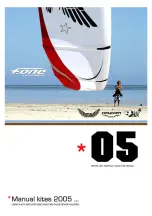
Brand: F-One Pages: 24

SkyRanger Nynja 600
Brand: Flylight Airsports Pages: 62
550
Brand: Eclipse Pages: 10
A5
Brand: ICON Pages: 836

Race
Brand: Cabrinha Pages: 37
IV
Brand: Lancair Pages: 53

Mystique EFL4905
Brand: E-FLITE Pages: 5
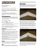
SST
Brand: Fancy Foam Models Pages: 3
VENTURA
Brand: ICP Pages: 13
JET
Brand: ICARO Pages: 17
QUIK
Brand: P&M Aviation Pages: 54
RV-12
Brand: Van's Aircraft Pages: 34
RV 12iS
Brand: Van's Aircraft Pages: 222
1970 150
Brand: Cessna Pages: 38
XA41
Brand: XtremeAIR Pages: 8
STOL CH750
Brand: Zenith Pages: 9

ALPINA 4
Brand: Ozone Pages: 32
ZU-NRC
Brand: The Airplane Factory, Inc Pages: 166


