13 |
P a g e
J Tech Photonics, Inc.
Pic-
Convert™ Board Instructions V2
.7
Copyright 6/13/17
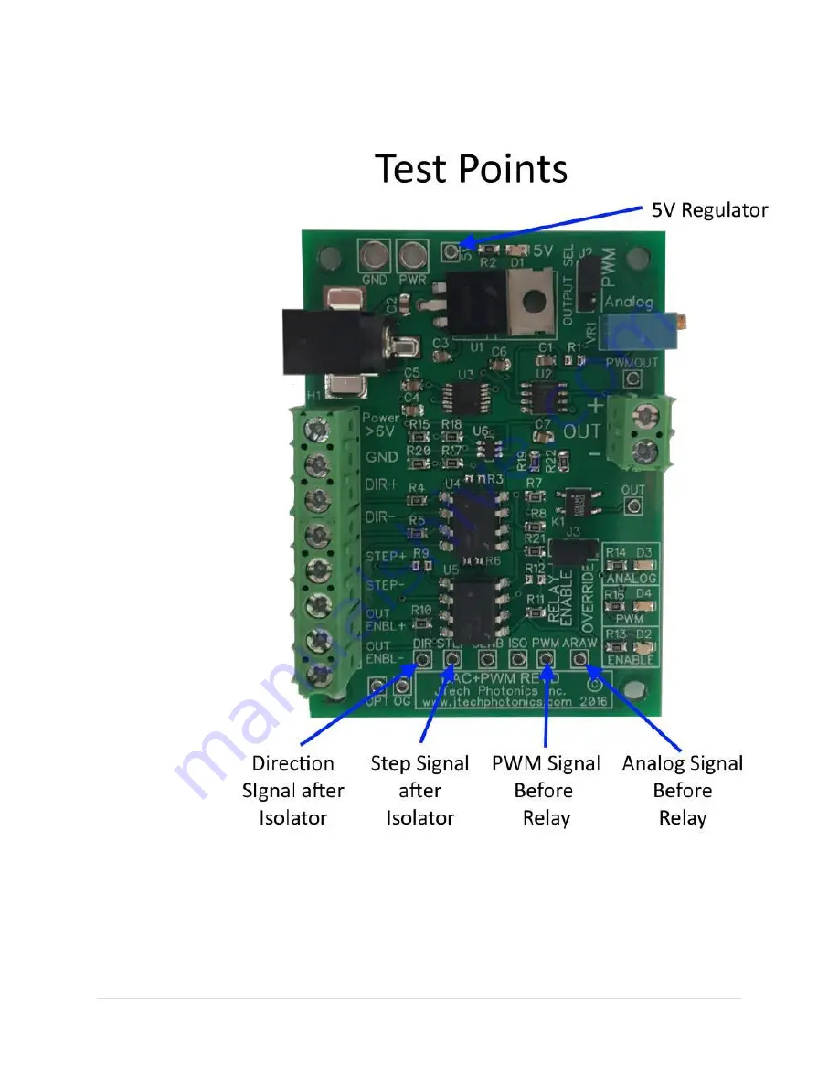
I picture showing the test points is below.
Page 1: ...or laser drivers PWM output for PWM modulated drivers Analog output for analog modulated drivers Output Enable Relay to control output with M03 M05 command Fully isolated inputs allow for more industr...
Page 2: ...d be easy to find Connection Overview INPUTS left side of the board Direction Direction encoder signal for the axis chosen in control software Direction Connect to the GND signal for your Breakout boa...
Page 3: ...24volts but make sure the regulator does not get too hot The regulator is the IC right next to the barrel power connector If needed for higher voltage operation a heatsink can be added via the screw...
Page 4: ...choose any extra axis your controller has or you can use the Z axis If you use the Z axis just remember to either disable your motors or take off the motor connections before you run it Now your laser...
Page 5: ...5 P a g e J Tech Photonics Inc Pic Convert Board Instructions V2 7 Copyright 6 13 17 100 Power 1 Power...
Page 6: ...provides a duty cycle or analog voltage output based on an increment from the step and direction output on your controller It is imperative that this output is linear for the 256 shades of greyscale...
Page 7: ...onnect them to the appropriate input screw terminals on the Pic Convert board You can also use another output to control the relay to enable the output of the board with the M03 M05 command This adds...
Page 8: ...lower on J2 If you want relay power control then choose it on J3 Connect the controller output M03 M05 signal to the Driver Enable input if you want to control the pass through power Connect the modul...
Page 9: ...l be 256 steps in this range Your feedrate will determine the darkness level at the maximum steps Faster lighter and slower darker To get the perfect results for your material you can first find the m...
Page 10: ...with the Pic Convert board Units are in INCHES Steps per inch 10000 Velocity Calculated by your machine controller Accel 30 Step Pulse 5 Direction Pulse 5 This makes your incremental move distance 0...
Page 11: ...eyboard jogging and a digital readout on the mach3 screen Units are in inches and example using the Z axis Max laser value 0 0255 Min laser value 0 Laser Off Command M05 if using the output relay Lase...
Page 12: ...alog is dim Solution That is the way it is supposed to be The board starts at 50 You need to jog the axis to lower or increase the value 3 I am loosing steps in my picture There are lines missing Solu...
Page 13: ...13 P a g e J Tech Photonics Inc Pic Convert Board Instructions V2 7 Copyright 6 13 17 I picture showing the test points is below...
Page 14: ...more ability to drive a signal Some break out boards have a spindle interface which have more power than standard lines I want to use a 5V power supply Will this work Most of the other USB or wall ad...
Page 15: ...steps on the STEP pin Now the digital potentiometer will DECREASE the duty cycle by 100 levels which puts the DUTY CYLCE now at 61 almost at half power This pixel was just supposed to be a little lig...
Page 16: ...amp For the 2 8W kit it is 1 5amps For the 3 8W kit it is 2 5amps This is frustrating to get to work Why is this so difficult This is an advanced method for engraving images and takes some time to mas...