


8670-5WB Manual – 10/2006
22
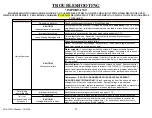
TROUBLESHOOTING
! IMPORTANT!
TROUBLESHOOTING SHOULD BE DONE BY A QUALIFIED ELECTRICIAN OR TECHNICIAN WITH POWER DISCONNECTED
WHENEVER POSSIBLE. PROCEDURES MARKED !CAUTION! REQUIRE THAT THE POWER BE ON AND MAY INVOLVE DANGEROUS
VOLTAGES.
Problem
Possible Cause
Solution
No power to machine
Check circuit breaker for machine. Reset if needed.
!CAUTION!
Inadequate power to machine
Verify proper service hookups. Air machine should have a
dedicated
120V, 20A, 60Hz
single phase service. Improper electrical service can lead to erratic behavior and may
damage components.
Improper timer setup
Verify timer is set properly using timer setup charts on pages 11-15.
Loose/Missing/Damaged wire
Verify integrity of wires. If possible, trace continuity between key components
(compressor, timer, coin mech, solenoid).
Check key components to isolate failure:
Timer:
Verify proper input voltage. Activate timer. If no output voltage is present
when timer should be active, replace timer.
Water solenoid:
Check voltage across the solenoid. Replace solenoid if proper
voltage (120VAC) is present and solenoid doesn't engage. If solenoid is stuck doesn't
disengage when voltage not present, disassemble and clean solenoid.
Coin mech:
Remove the wires leading to the timer from the coin mech and tap them
together one time for each coin necessary to start the timer. If machine starts, replace
the coin mech.
Remote Starter:
Test transmitter batteries and replace if needed. Remove receiver
cover and verify proper voltage across terminals 1 and 3 (24VAC). If proper voltage is
present and transmitter batteries are good, follow instructions to program transmitter
and receiver. If remote starter still will not function correctly, replace with new remote
system.
Compressor: !CAUTION - DANGEROUS VOLTAGE LEVELS PRESENT -
QUALIFIED ELECTRICIANS ONLY!
Bleed remaining air from line and verify proper
voltage (120VAC) across compressor leads. If proper votage is present and
compressor will not start, replace compressor. If compressor starts with no pressure in
air line but will not start when pressure is present, replace unloader valve.
Timer giving
inaccurate time
Improper timer setup
Reset the timer according to instructions on pages 11-15.
Loose wiring
Inspect wiring from coin mech and remote start to timer to verify proper connection.
!CAUTION!
Damaged timer/Coin mech
Isolate timers from coin mech and remote start. If timer continues to run after the
maximum possible timer setting, replace timer. If unit times out and turns off, coin
mech or remote start may need to be replaced.
Unit runs
continuously and will
not shut off
!CAUTION!
Component failure
Unit will not start
Summary of Contents for 8670-5WB
Page 1: ......
Page 7: ...8670 5WB Manual 10 2006 7 Figure 1 Installation footprint for 6025 hose reel base ...
Page 8: ...8670 5WB Manual 10 2006 8 Figure 2 Mounting and routing detail ...
Page 9: ...8670 5WB Manual 10 2006 9 Figure 3 Electrical installation detail ...
Page 10: ...8670 5WB Manual 10 2006 10 Figure 4 Cabinet and hose reel base dimensions ...
Page 18: ...8670 5WB Manual 10 2006 18 ...
Page 19: ...8670 5WB Manual 10 2006 19 ...
Page 20: ...8670 5WB Manual 10 2006 20 ...
Page 21: ......