M
AINTENANCE
turn clockwise in quarter turns - the limit value
is increased,
turn counter-clockwise in quarter turns - the
limit value is reduced,
5. Secure threaded pins with the lock nuts. Do
not turn the threaded pins any more as the
setting will be altered.
6. Check the limit value for correct setting.
7. Install the gearbox cover.
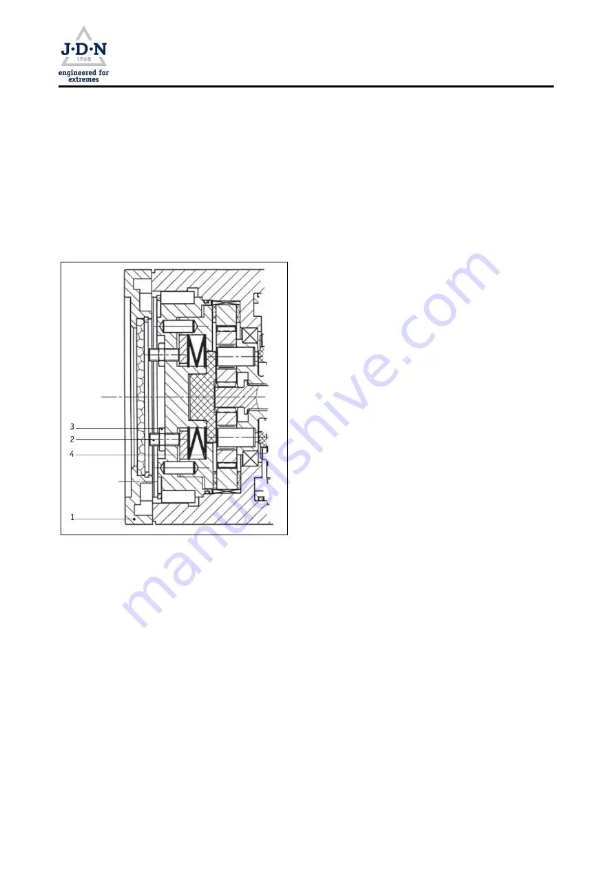
Figure 14: Adjusting overload protection
Re-adjust the overload protection
The adjust-
ment method described here is based on the at-
tachment of test loads (
,
→
Figure 14). The over-
load protection is located on the gearbox.
1. Unload the hoist.
2. Detach the gearbox cover
(1)
vfrom the gear-
box in order to gain access to the threaded
pins
(2)
with lock nuts
(3)
located behind it.
3. Loosen the lock nuts. Screw out the threaded
pins until the disc springs
(4)
are completely
free of pre-tension.
4. Then loosely screw in the threaded pins by
hand to the stop. Unscrew the lock nuts suffi-
ciently far back beforehand.
5. The limit value for reaching at least 110% of
the load capacity is set at approximately 2
turns. Screw in the three threaded pins suc-
cessively in small steps by approximately
1/2 turn. With this pre-adjustment after re-
assembly, first let the safety clutch take effect
for approx. 5 seconds without the load (load
hook on the upper end position with the motor
running). Then let the load hook run for ap-
prox. 10 seconds without a load so that the
outlet air cools the clutch down.
6. Secure threaded pins with the lock nuts. Hold
the threaded pins tightly in the process.
7. Check the limit value for correct setting, cor-
rect if necessary.
8. Install the gearbox cover.
9. The adjusting and inspecting result arrived at
by qualified personnel must be entered in the
inspection log.
Doc.-No.: VA049318-20-OM-EN-0319-64-6
Page
53
of 64


