


powered by air !
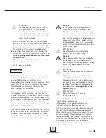
M A I N T E N A NC E
Page 37
Should the wear limit be reached prematurely, the
actual compressed air pressure must be checked with
the device switched on (the brake drags in the event
of insufficient pressure).
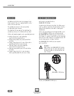
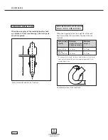
Checking vane wear (see illustration
Checking vane
wear,
page 37). When the air motor vanes are worn,
the motor power and consequently the lifting perfor-
mance of the JDN Air Hoist are reduced. Replacing
the vanes together with the starting aids.
A S S E M B LY / M O T O R L U B R I C AT I O N
Fit the brake disc, inserting the anti-twist device
(pin), lightly coat brake side with high-performance
grease (JDN ART. No. 11901).
Insert cylinder liner, align on the bore of the anti-
twist device with the pin before inserting, lightly
coat cylinder liner on the inside with high-perfor-
mance grease.
Lightly coat the vane slots, cylinder and end surfaces
of the rotor with high-performance grease and insert
rotor into the housing bearing with the clutch side
first.
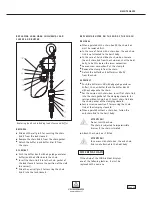
Coat the vanes lightly with high-performance grease
and push into the rotor slots with the starting aids.
Lightly coat the entire brake piston surface including
its seal with high-performance grease and push it
into the cylinder liner with the braking surface first;
note the correct position of the eccentric bore.
Lightly coat the outer rotor bearing (needle bush)
with high-performance grease as well.
Insert the brake springs into the bores of the
brake piston.
Install the cover with bearing, ensure correct seating
of the brake springs and locating pins to the motor
housing and to the brake piston, screw back the
adjusting bolts
13
beforehand.
Do not tighten the four adjusting bolts
13
after bolt-
ing the cover in place; only screw them in loosely to
the stop in the cover, screw back the lock nuts
14
sufficiently beforehand.
Then screw back the adjusting bolts
13
45° from the
stop, hold and lock with the nuts
14
. For operation
in areas with ambient temperatures exceeding 30° C,
the adjustment must be performed with the hoist
warmed up accordingly.
Attach the nameplate.
AT T E N T I O N !
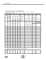
Refer to tightening torques table,
page 45.
C AU T I O N !
Check the braking action of the hoist under
load (run in the brake by performing several
hoisting cycles, then assess) prior to initial
operation. Check the motor power. In the event
of low motor power, reset the adjusting bolts.
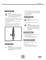
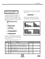
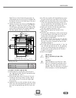
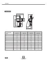
Checking vane wear
Vane
Rotor
Cylinder liner
Brake piston
V2 max. = 0.2 mm
•
•
•
Brake disc
•
V1 max. = 0.2 mm
R
•
Lmax = R – (V1 + V2)
Lmin = R – (V1 + V2) – 0.3 mm = Lmax – 0.3 mm
L
L h
L
h
MINI 125 / 250
≥
14 mm
MINI 500 / 1000
≥
19 mm
Summary of Contents for JDN mini 1000
Page 47: ...powered by air NOTES Page 47 ...


