


PR_I020/2023-08-11-EN
Revision: 5
14
General stove installation steps
Location considerations
We recommend installation of this appliance by a certified
installer.
Consideration must be given to:
➢
Safety;
➢
Traffic flow;
➢
Convenience;
➢
Chimney and chimney connector required;
➢
Draft.
Drawing your installation plan on paper is a good way to
avoid mistake.
THESE STOVE MODELS ARE NOT
APPROVED TO INSTALL IN AN ALCOVE
Write on the plan:
•
Exact dimensions for clearances to combustible
material;
•
Exact dimensions of the floor protection;
•
Measurements of the chimney location. (If it not already
installed. Be sure to have all clearances recommended
by the factory-built chimney manufacturer to pass
through the ceiling and roof).
We recommend that a qualified building inspector and your
insurance company representative review your plan before
and after installation.
General steps of installation
1) Read the entire installation manual before installing
and using your stove.
2) Choose a spot where to install your stove. Read
section about floor protection dimension, localisation of
stove over the floor protection plate and combustible
material clearance. Once you have decided where to
install the stove, mark the roof at the center of chimney.
o
To be sure that the vertical center of the chimney,
use a plumb line and mark the center on the floor.
3) Check if it possible to pass chimney without damaging
the structural integrity of your house. If so, you have to
move the location of the stove while keeping the
minimum clearance or more to be sure. If you can’t
move the stove and have to cut through a beam, make
sure to keep the structural integrity of your house by
following state of the art and National building code.
o
We recommend installation of this appliance by a
certified installer.
Note
:
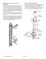
This appliance has to be connected to 6 inches
(15.24 cm) factory build chimney HT UL 103 or CAN/ULC
S629 compliant or a 6 inches (15.24 cm) masonry chimney
with a homologated sleeve inside. Do not install the
chimney directly at the outlet of the appliance. A chimney
connector (flue pipe) is required unless the appliance is
specifically approved for that type of installation.
4) Install the chimney following the manufacturer
instruction.
5) Put the stove directly on the floor aligned vertically with
the center of chimney and trace the side of the stove
on the floor and remove it.
6) Trace the dimension of protection plate on the floor.
There must be 8 inches (20.3 cm) clearance from the
side and the back of the stove. From the front of the
door opening, there must be a clearance of 18 inches
(45 cm). If the space heater meeting the requirement
of CAN/ULC S627 is suitable for installation on a
combustible floor and do not require radiant floor
protection.
7) Install the floor protection plate inside the mark (It must
be non-combustible).
8) Put the stove on the protection floor plate and respect
the offset clearance set at step 6. Be sure to center the
stove under the chimney. We recommend to fix the
stove to the floor with bolt in the slot made for this
purpose in the legs. In a mobile home, it is obliged to
fix the stove.
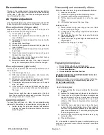
9) If you have an outside air inlet, you must use 4 inches
(10.16 cm) flexible aluminum pipe. The pipe must be
sealed with thermal resistant sealant and it has an air
intake with grate approved for this purpose.
10) Install the chimney connector on the stove. The pipe
must be fixed with at least 3 screws on the stove collar,
each chimney connector and the chimney collar.
Note
:
The single wall chimney connector must be 6 inches
diameter and have a minimum thickness of 24 gauge (0.025
inches 0.64 mm). Do not use galvanised steel chimney
connector.
.
Summary of Contents for ULTIMATE TOR 2015
Page 4: ...PR_I020 2023 08 11 EN Revision 5 4 Rating plate...
Page 5: ...PR_I020 2023 08 11 EN Revision 5 5 Appliance Dimension...
Page 13: ...PR_I020 2023 08 11 EN Revision 5 13 Firebox configuration and part list...
Page 28: ...PR_I020 2023 08 11 EN Revision 5 28 Annex 1 Door assembly Square Door Arc Door...


