6
2010-05/MU/ROVINS-001-B
7
2010-05/MU/ROVINS-001-B
STEP 1- INSTALLING ROVINS
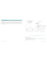
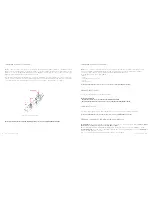
ROVINS is fixed onboard using six CHC M6 screws. It can be installed with any orientation with respect to the vessel (see
the definition of the vessel reference frame hereafter). The alignment of the unit is performed by means of the two cen-
tering pins located on the bottom plate of the ROVINS. You will find on Figure 1 all the mechanical information necessary
to fix ROVINS. All inertial measurements are default performed with respect to ROVINS reference frame (X1, X2, X3). This
reference frame is defined in Figure 1. Motion sensing measurements are default measured at ROVINS Center of Mea-
surement P (see Figure 1).
Recommendations and Note
•
Temperature in operation must be in the range -20 °C to 55 °C
•
The dimensions of the ROVINS housing are ((l x
ø
) in mm ): 374 x 213. There must be enough place for the wire way
on the connector side of ROVINS
•
The weight of ROVINS is 14.6 in air and 4.65 in sea water
Figure 1 – Definition of ROVINS Reference Frame (X1,X2, X3) and P center of measurements


