background image

20

2010-05/MU/ROVINS-001-B

21

2010-05/MU/ROVINS-001-B

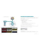
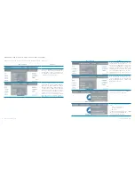
WEB-BASED USER INTERFACE - MENUS AND OPTIONS OVERVIEW

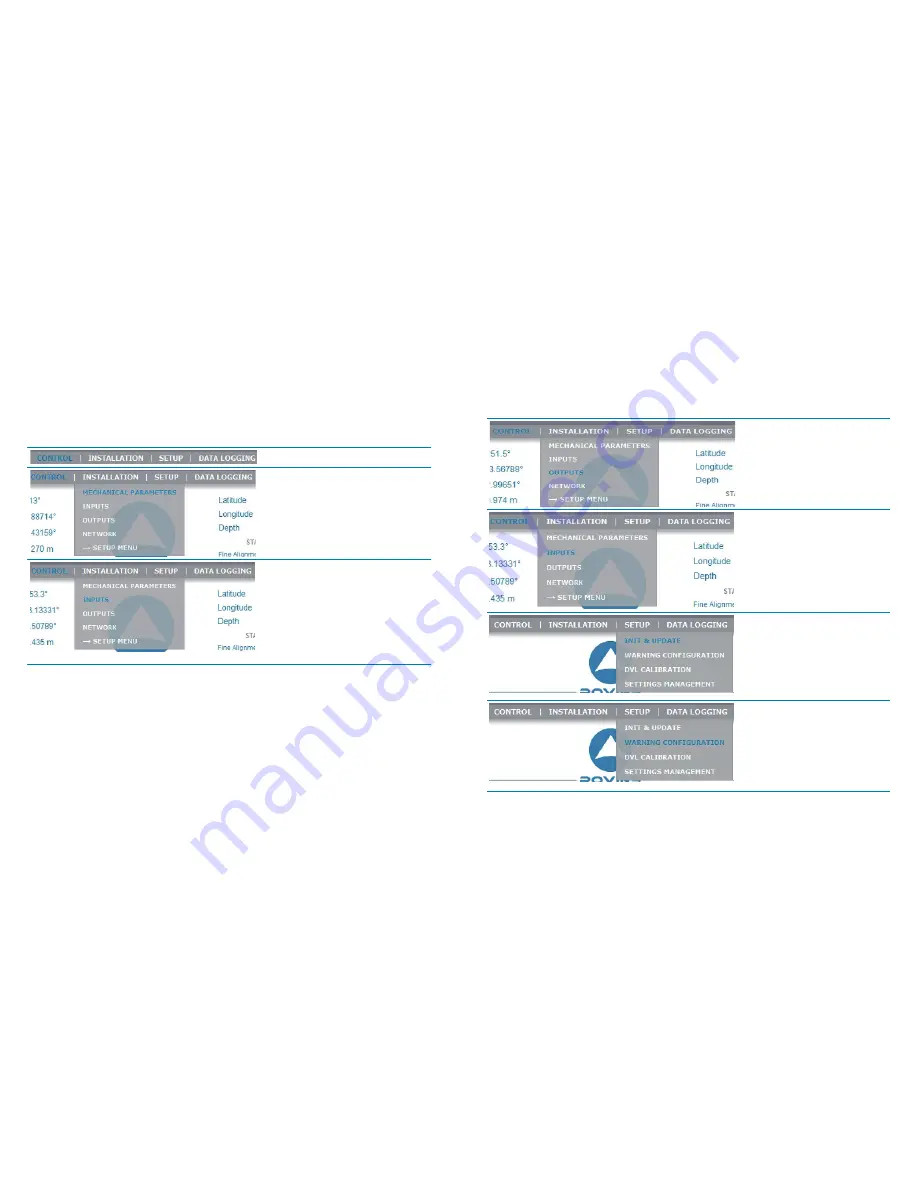
Find hereafter all the menus and options of the WEB-based User Interface and their uses

Menu /options

Used to …

Define  the  ROVINS  orientation,  possible 

roll,  pitch  and  heading  misalignments, 

primary  and  secondary  lever  arms  useful 

to compute the heave and position for the 

output protocols that provide it

Define the couple (external sensor or UTC, 

input  link):  the  protocol  used  to  input  the 

data, the serial (parity, baud rate, standard 

(RS232 or RS422) and stop bit) or Ethernet 

(transport layer, IP address, Port number) 

parameters, and the external sensor para-

meters (lever arms, misalignments (for the 

DVL), beacon selection (for the USBL)

Define  the  Time  synchronization  settings 

(UTC): pulse input selection for the PPS si-

gnal, the protocol to use for the PPS signal

Menu /options

Used to …

Define  the  outputs:  the  protocol  used  to 

output the data, the lever Arm to use, the 

data rate or the input pulse to use to syn-

chronize the output data, the serial (parity, 

baud rate, standard (RS232 or RS422) and 

stop bit)or Ethernet (transport layer, IP ad-

dress, Port number) parameters, the pulse 

output to output the envelop, the heave fil-

ter to use

Define  the  Network  parameters  for  com-

munication through a serial link (PPP op-

tion) or through Ethernet one (DHCP client 

mode activation, ROVINS IP       address and 

Network mask to use)


Enter the initial position, save it, update it


Choose the Zero Velocity mode


To be informed in case of warning or er-

ror for


UTC synchronization loss


Position sensor loss


Speed loss


To generate a warning when the heading 

and/or the position standard devia 

tion cross a defined threshold

Summary of Contents for Rovins

Page 1: ...Quick Start Guide Quick Start Guide Rovins gyro to ins ...

Page 2: ... required before beginning the positioning Contents OBJECTIVE 01 CONTENTS 01 CONVENTIONS 02 ROVINS SYSTEM OVERVIEW 03 VERIFICATION OF PACK CONTENTS 03 BASIC INSTALLATION 03 STEP1 INSTALLINGROVINS 05 STEP 2 ACTIVATING THE PRODUCT LICENSE 10 STEP 3 CONFIGURING ROVINS 19 STEP 4 NAVIGATING WITH ROVINS 24 MORE 25 CUSTOMER SUPPORT 29 IXSEA CONTACT 30 ...

Page 3: ... traditional navigation approaches ROVINS is delivered with a powerful and easy to use WEB Based User Interface which allows a complete configuration You will find in the shipping case a Packing List detailing all the items delivered This packing has been completed and checked by IXSEA shortly before shipment and should match the contents of the pack you have received However we recommend that you...

Page 4: ...e PC ROVINS communication parameters To configure the GPS serial or Ethernet input parameters lever arm Configuring To define the initial position To activate the GPS i e to take the GPS data into account by the Kalman filter To activate the license code To define the Time Synchronisation system Step 3 Navigating with ROVINS Step 4 5 min Heading standard deviation 0 1 ...

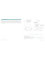
Page 5: ... necessary to fix ROVINS All inertial measurements are default performed with respect to ROVINS reference frame X1 X2 X3 This reference frame is defined in Figure 1 Motion sensing measurements are default measured at ROVINS Center of Mea surement P see Figure 1 Recommendations and Note Temperature in operation must be in the range 20 C to 55 C The dimensions of the ROVINS housing are l x ø in mm 3...

Page 6: ...tch and roll Once the axis XV2 lies in the local ho rizontal plane the pitch is the angle between the axis XV1 of the vessel and its projection in the local plane This angle is default defined positive in the direction of the axis XV2 i e when the boat bow is down It varies from 90 to 90 The figure above is an illustration of the pitch angle in case of null roll Vessel reference frame True Heading...

Page 7: ...o the serial link A of ROVINS GPS Output protocol on serial link A GPS like PPS time synchronization pulse from the GPS cabled on the Pulse input A of ROVINS In this case the workstation establishes a PPP connection with ROVINS Refer to the ROVINS User Manual to know how to configure this PPP connection Electrical Connections GPS PPS optional for Time synchonization Serial Link Case when Ethernet ...

Page 8: ... the workstation is performed directly through the Ethernet link ROVINS Web based User Interface is then launched from the WEB browser hosted on the workstation Its URL address is 192 168 36 1xx xx being the two last numbers of the ROVINS serial number The Control Pages opens During the first seconds the IXSEA logo is flashing gray blue indicating that the Web based User Interface is loading the i...

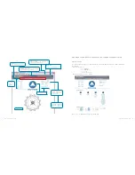
Page 9: ...lor and verbose display Latitude Longitude and Depth or UTM positions and Depth data Heading Roll Pitch Heave and Speed data Compass area UTM northing 4784416 50 m UTM easting 714025 03 m Depth 25 30 m IXSEA logo handling A click on the IXSEA logo opens the detailed status activation pop up window and the compass disappears This window Sums up the status of The input ports The output ports The sys...

Page 10: ...ur needs Scrolling list selection By selecting it directly in the scrolling list Color Definition Grey inactivity Flashing Grey Blue System Configuration during initialization for example Blue Activity nominal operation Orange Activity warning Red Activity alarm Text box By typing it in the dedicated area Note You can also use the up arrow and down arrow keys to increase or decrease the numerical ...

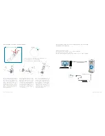
Page 11: ...ss is repeated Reset to factory settings the customized configuration is lost Product License Activation only in case of upgrade Ask for the activation code click on maintenance menu on the ROVINS Web based User Interface To recover the activation code using the Contact Support button send a message to IXSEA support giving your ROVINS license ID Enter the recovered activation code in the dedicated...

Page 12: ...ime synchronization settings UTC pulse input selection for the PPS si gnal the protocol to use for the PPS signal Menu options Used to Define the outputs the protocol used to output the data the lever Arm to use the data rate or the input pulse to use to syn chronize the output data the serial parity baud rate standard RS232 or RS422 and stop bit or Ethernet transport layer IP ad dress Port number...

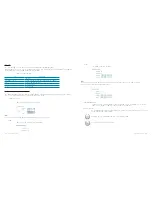
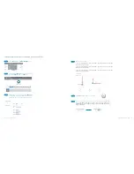
Page 13: ...CONFIGURING ROVINS Configuring the ROVINS Orientation with Respect to the Vehicle As ROVINS can be installed with any orientation with respect to the vehicle ROVINS axes orientation can be different from vehicle axes orientation with 90 degrees rotations of any of the ROVINS axis with respect to the vehicle axes Choose MECHANICAL PARAMETERS under INSTALLATION Menu Click on Restart button in the wa...

Page 14: ...distance from the ROVINS center of measurements to the GPS along axis 1 of the illustration LV2 is the signed distance from the ROVINS center of measurements to the GPS along axis 2 of the illustration LV3 is the signed distance from the ROVINS center of measurements to the GPS along axis 3 of the illustration Step 5 Step 6 Step 4 Choose INPUTS under INSTALLATION Menu Associate GPS to INPUT A by c...

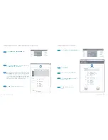
Page 15: ... choose Ethernet for the Physical Link then select Pulse B for Synchro In and the desired protocol For a serial link the pulse input will come from pulse input A choose Serial for the Physical Link then select Pulse A for Synchro In and the desired protocol Step 1 Step 4 Step 2 Step 3 Choose OUTPUTS under INSTALLATION Menu Click on Output A Choose GPS like in the Protocol list Select the Physical ...

Page 16: ... in meters Click OK to validate and save your choices Step 1 Step 2 Step 3 Step 4 Entering the initial position is only necessary if no GPS is available upon starting ROVINS Once saved by clicking on OK button the entered position is used at next ROVINS start or the UTM coodinates of this position Click options menu In the Coordinate System area Either select Latitude longitude option Or UTM optio...

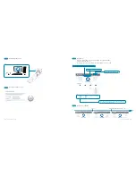
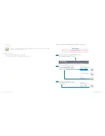
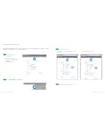
Page 17: ...INS performs its coarse alignment ROVINS inertial sensor data accelerometers and gyrometers are computed to estimate heading roll and pitch angles At sea it is recommended that the system is kept as steady as possible during coarse alignment oscillations around a mean position are permitted but accelerations should be avoided Leaving the vessel adrift for 5 minutes would lead to satisfactory condi...

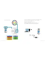
Page 18: ...r data passe through a rejection filter before being incorporate into ROVINS main computation Kalman filter The following external sensors can be added A DVL A LBL An USBL up to three beacons A CTD A depth sensor For more details about the external sensors refer to part 4 of the ROVINS User GUIDE Ethernet Input output Five Ethernet inputs outputs are available on ROVINS For more details about The ...

Page 19: ... external sensor is connected For more details about ZUPT mode refer to part 4 of the ROVINS User Guide customer support THE WORLDWIDE 24 7 TELEPHONE SUPPORT LINE NUMBERS ARE EMEA 33 0 1 30 08 98 98 USA 1 888 660 8836 toll free ASIA 65 6747 7027 To contact customer support for any IXSEA products a general mail box is available with the following address support ixsea com ...

Page 20: ... 88 33 0 1 30 08 88 01 IXSEA BV The Netherlands 31 0 23 750 5110 31 0 23 750 5111 IXSEA GmbH Germany 49 0 511 123 59575 49 0 511 123 59576 IXSEA Ltd Main office IXSEA Ltd Aberdeen office United Kingdom 44 1730 260222 44 1224 355160 44 1730 260333 IXSEA LLC United Arab Emirates 971 4 3117135 971 4 3328860 IXSEA Inc Usa 1 888 660 8836 1 781 937 8806 IXSEA Pte Ltd Singapore 65 6747 4912 65 6747 4913 ...

Page 21: ...38 2010 05 MU ROVINS 001 B 39 2010 05 MU ROVINS 001 B PERSONAL NOTES PERSONAL NOTES ...

Reviews: