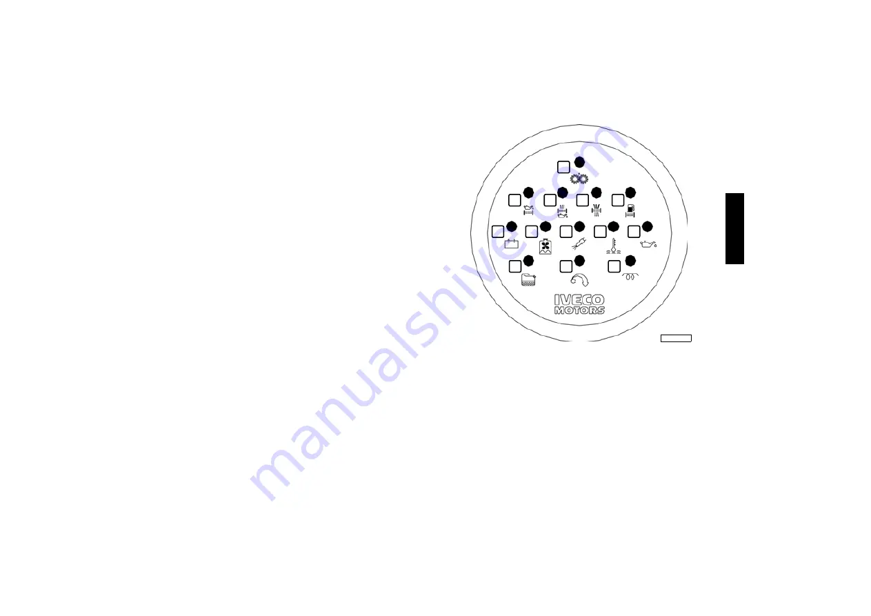
Iveco Motors N45 MNA M10.00 Use And Maintenance Download Page 16

15

ENG

L

ISH

RECOGNISING ALARMS

IVECO MOTORS on-board control panels with analogue instruments
are fitted with an electronic module that includes the indicator lights
and the interface, timer and alarm storage circuits.
The figure illustrates the dial and the key indicates the meaning of the
alarm signals sent by all the indicator lights; some types of engine and
relevant equipment only make some of the above mentioned
functions available.
If the Boatyard uses different technical options there may also be
changes to the above.

Operation

When the key switch is turned to position 

8B

 the signals and alarms

module will perform an efficiency test on all the indicator lights, lasting
5 seconds, with the exception of the “Pre-lubrication”, “Pre-post
heating”, “EDG system malfunction” indicators, and simultaneously the
beeper sounds.
It is possible to stop the beeper before the end of the test, by pressing
the relevant button.
During start-up and for the following 15 seconds, all alarm functions
are disabled; after this period, each alarm detected by the sensors
provided on the engine will result in the relevant indicator flashing and
a simultaneous warning sound from the beeper. If the beeper is
disabled by pressing the relevant button, the indicator light will turn on
without flashing and the alarm will be stored until the engine is next
stopped. 

1. Maximum allowed rotation speed exceeded (on request) - 2.
Water in the fuel pre-filter - * 3. Engine coolant level low - 4.
Alternator malfunction - *5. Oil filter blocked - *6. Oil vapour filter
blocked - *7. Pre-lubrication in progress - 8. Air filter blocked -
*9. Fuel filter blocked - 10. Coolant temperature high - 11. Oil
pressure low - *12. Pre-post heating - *13. Malfunction in EDC
electronic injection system.

*Alarm functions not available with standard setup.

1

2

12

11

10

13

3

4

5

6

8

9

7

04_234_N

Summary of Contents for N45 MNA M10.00

Page 1: ......

Page 2: ...erations to be carried out in order to allow the engine and or its fittings to perform in a certain way In some cases they will be dependent on the configuration of the commands and the set up of the...

Page 3: ...ol panel 12 Recognising alarms 15 For proper use of the engine 16 Special warnings 16 Running in 17 Refuelling 18 CONTROLS AND MAINTENANCE 19 Maintenance personnel 19 Accident prevention 19 Frequency...

Page 4: ...hen using the engine so as to avoid damage to persons or property as a result of improper or incorrect behaviour The engines must only be used for the purposes indicated by the Manufacturer Any tamper...

Page 5: ...t 4 480 cm3 Air system Natural aspiration NA Injection type Direct with VE rotating pump Engine direction of rotation Anticlockwise seen from flywheel side Dry weight 495 kg Electrical system 12 V 24...

Page 6: ...t exchanger 12 Starter motor 13 Removable anode 14 Sea water outlet manifold Engine N40 ENT M10 1 Coolant tank pressurisation cap 2 Oil dipstick 3 Water heater system manifold 4 Air filter 5 Oil vapou...

Page 7: ...6 700 cm3 Air system Natural aspiration NA Injection type Direct with VE rotating pump Engine direction of rota tion Anticlockwise seen from flywheel side Dry weight 600 kg Electrical system 12 V 24 V...

Page 8: ...t exchanger 11 Removable anode 12 Sea water outlet manifold 13 Starter motor Engine N67 MNA M15 1 Coolant tank pressurisation cap 2 Water heater system manifold 3 Air filter 4 Fuel outlet towards the...

Page 9: ...0 cm3 Air system Supercharged and aftercooled Injection type Direct with VE rotating pump Engine direction of rotation Anticlockwise seen from flywheel side Dry weight 600 kg Electrical system 12 V 24...

Page 10: ...13 Coolant drainage plug 14 Connection to battery positive terminal 15 Electrical starter motor 16 Removable anode 17 Sea water outlet manifold Engine N67 MNT M28 1 Fuel filter 2 Fuel inlet from tank...

Page 11: ...rk on them underline a potential danger Lifting point engine only Fuel Cap on the fuel tank if there is one Oil Cap Oil dipstick Danger of burning Expulsion of hot water under pressure Danger of burni...

Page 12: ...t manufactured by IVECO MOTORS The start up and shut down operations described below apply to an on board control panel manufactured by IVECO MOTORS if the vessel is fitted with an instrument panel th...

Page 13: ...ation on how to interpret this test and indications on the module are given in the relevant paragraph 4 Turn the key to position 8C once the engine has started release the key quickly and do not accel...

Page 14: ...f the alternator recharge and low oil pressure indicators At the same time check that the indicator test has been performed successfully information on how to interpret this test and indications on th...

Page 15: ...d button 6 on the control panel The main IVECO MOTORS control panel for engines equipped with an excited device on request or as prescribed by the Certification Body is stopped by pressing the red but...

Page 16: ...the beeper sounds It is possible to stop the beeper before the end of the test by pressing the relevant button During start up and for the following 15 seconds all alarm functions are disabled after...

Page 17: ...hold The oil pressure remains within normal values SPECIAL WARNINGS Coolant temperature high If the temperature indicated on the instrument is considered too high or if the alarm is displayed reduce s...

Page 18: ...m Periodically check particularly during the winter to ensure that the batteries are clean and in full working order checking and topping up as indicated in the section CONTROLS AND MAINTENANCE always...

Page 19: ...tinguish different classes of diesel fuel identifying the characteristics of those best suited to low temperatures It is entirely up to the Oil companies to comply with these regulations which foresee...

Page 20: ...in the vicinity of engines or moving parts Always wear protective gloves and goggles when filling up batteries with acid solution refuelling with inhibitors or antifreeze replacing or topping up lubri...

Page 21: ...Daily Check oil level in marine gear Daily Check engine coolant level Daily Check exhaust pipe s for damage Daily Drain water from the fuel filter or pre filter 150 hours 1 Check top up electrolyte l...

Page 22: ...air and water sections engine coolant sea water heat exchanger clean the sea water section optional sea water marine gear oil heat exchanger clean the sea water section 7 Must be performed annually ev...

Page 23: ...t the battery batteries before any electrical operations 8 Contact the Boatyard before installing electronic equipment on board two way radios echo sounding equipment etc HOW TO PROCEED Check oil leve...

Page 24: ...rm this control even if no alarm is shown on the on board control panel Proceed with the engine stopped Place a container under the filter or pre filter to collect the fluid Unscrew the tap plug 1 in...

Page 25: ...pressed air through the filter element from the inside outward maximum pressure 200 kPa or wash with water only avoiding the use of detergents do not use die sel Replace the filter if any breakages ar...

Page 26: ...o as to avoid the risk of burning Unfasten the screws and remove the cover 5 to the filter compartment Remove the two filters and check them for deposits if any deposits are found replace them Replace...

Page 27: ...low temperature Only use filters with a filtration level equivalent to the ones you are replacing see section FREQUENCY Remove the filter by unscrewing it Check that the new filter has performance lev...

Page 28: ...d at a low temperature Remove the pre filter by unscrewing it Check that the new filter has performance levels that satisfy the needs of the engine e g by comparing them with the old one Damp the new...

Page 29: ...the risk of burning Provide suitable containers to ensure that no coolant is dispersed into the environment Remove the plugs on the circuit components and wait until the circuit has drained completely...

Page 30: ...l in the section ENGINE TECHNICAL DATA and marked on the engine with special stickers Lifting must be carried out using a rocker arm that keeps the metal cables supporting the engine parallel using al...

Page 31: ...onment The materials listed below must be handed over to specialised Collection Centres the laws in force in the various Countries foresee severe penalties for transgressors Starter batteries Used lub...

Page 32: ...arter motor with a positive voltage equivalent to the rated voltage of the system using a conductor provided for that purpose 5 Nebulise approximately 60 g of 30 M protective oil 10 g per litre displa...

Page 33: ...rger suction inlet to the air filter 5 Connect the fuel circuits to the vessel s fuel tank completing the operations as indicated in point 4 of PREPARING THE ENGINE FOR A LONG PERIOD OF INACTIVITY Dur...

Page 34: ...flames on the burned person s clothing by throwing water over them using a powder fire extinguisher without directing the jet at the person s face covering with blankets or rolling the victim on the g...

Page 35: ...s necessary 1 In the event of bleeding keep the edges of the wound pressed together until help arrives 2 If there is any suspicion of a fracture do not move the injured part and only move the patient...

Page 36: ...35 ENGLISH 6 6 6 6 6 6 6 6 PLQHUDO EDVH 6 VHPLV QWKHWLF EDVH 6 VHPLV QWKHWLF EDVH 6 V QWKHWLF EDVH 6 V QWKHWLF EDVH...

Reviews: