!
Operational principal
The ED3-AT SkidWeigh Plus operational principal is based on the hydraulic pressure transducer mounted in the vehicle
lifting hydraulic circuit that will automatically activate the “weighing cycle / specific algorithm ” every time a skid load is
lifted just above the ground. The increase in pressure is converted in an electronic signal at the sample rate of 16000
readings which is converted into a load weight reading.
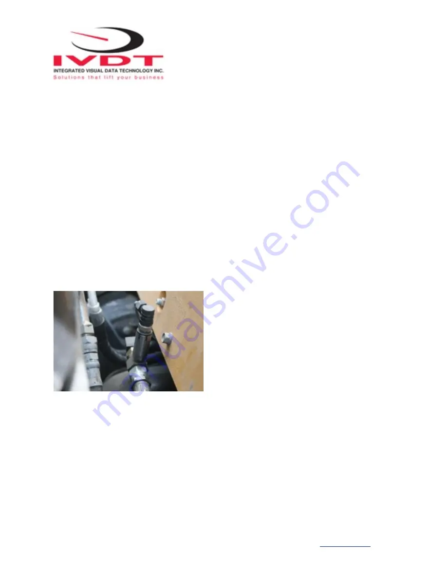
Pressure transducer installation
The pressure transducer must be installed in the lifting hydraulic line
between the lift control valve and lift
cylinder(s).
Mount a T-piece in hydraulic line. In some cases you can install the pressure transducer in the flow divider,
drilling and tapping for 1/4”-18 NPT male in spare plug (if only single or double mast configuration) or in the body of the
flow divider. Also, you can drill and tap on any “larger elbow” that might be available in the hydraulic lifting circuit found
in vehicles with larger hoses to accommodate larger vehicle lifting capacities.
Pressure transducer installation precautions
Before installation of the pressure transducer the hydraulic lift circuit must be pressure free.
There are two ways to do that:
1. Place the forks on the ground in their lowest position and
make the hydraulic system pressure free by tilting the mast
forward. The chain(s) should be slack.
2. Lift the forks and position them on the top of a supporting
fixture. Start lowering the lifting cylinder into its lowest position.
Be sure that chain(s) are slack.
Make sure that that installed pressure transducer will not touch
any moving parts or assembly of the vehicle while in normal
operation. Pressure transducer has 1/4”-18 NPT male thread.
Use thread seal to ensure tight fit.
Selecting the mounting location for digital indicator
Use the mounting bracket with the anti vibration mount and fasten digital indicator on the vehicle dashboard or side
railing preferably on the right hand side. There are many examples of mounting locations that will depend on the vehicle
model. However, additional mounting items such as a flat brackets may be needed to help secure the unit to upper right
corner of the guard or side railing.
Choose the correct location and make sure that:
- Indicator is visible and within reach of the operator
- Location so that operator does not hit a head
Integrated Visual Data Technology Inc. 3439 Whilabout Terrace, Oakville, Ontario, Canada L6L 0A7


