background image

 CMTinyCMTinyIQ_UM_9752097710_NL_D_GB_F_V1_1 


61


GB 


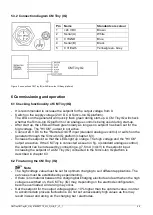
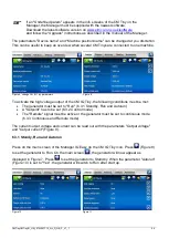
With the 

 buttons you can scroll through the various pages. The following data on the 

operation can be found here: 
- Output voltage (kV): Indicates the current value of the high voltage on the HV output,  
  see chapter 6.3 
- Output current (mA): Indicates the current value of the current on the HV output, see   
  chapter 6.3 
- Last warning: date and time of the last occurred Warning 
- Last alarm: date and time of the last occurred Alarm 
- Arcs per minute: displays the number of arcing per minute, see chapter 6.3.7 
 
If a Sensor IQ Easy is connected to the CM Tiny IQ, the display will also show: 
- Web voltage (kV): the current average charge measured by the active segments of  
  the sensor bar, see chapter 6.3.6 
- Web voltage peak (kV): the maximum charge measured by the active segments of  
  the sensor bar, see chapter 6.3.6 
 

7.2.2 Graphics tab 

 
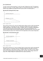
The Graphics tab graphically shows the operation as function of the time. 
- Blue  : the output voltage at the HV output (kV). 
- Yellow : the output current an the HV output (mA). 
 
If the screen is clicked, the screen will “freeze”, and "On hold" will show on the display. Clicking 
the screen again will display the current value. 
 

7.2.3 ActionLog tab 

 
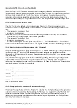
In the ActionLog tab, the changing status of the CM Tiny IQ is logged step-by-step. This is 
indicated including the date and time the status change has occurred. The main messages are: 
-HV OK: the generator is turned on and is functioning properly 
-HV NOT OK: the generator is turned off or the high voltage doesn’t function properly 
- REMOTE ON: 
- REMOTE OFF: 
In the Maintenance tab (Figure 19) the ActionLog tab can be emptied. 

 
7.2.4 DataLog tab 

 
In the DataLog tab, all available measurement data of the CM Tiny IQ is logged at fixed times. 
Main measurement values are: 
- U- (kV): the voltage on the high voltage output 
- I- (mA) current on the high voltage output 
- t (°C): the internal temperature of CM Tiny IQ 
- U (V): connection voltage of the CM IQ Easy 
 
In the Maintenance tab (Figure 19) the DataLog tab can be emptied. 
 
If the parameter "Data logging" is activated in the manager and the CM Tiny IQ (figure 11), 
these log values will also be saved in the log file of the Manager IQ Easy. The interval between 
logging is determined by the parameter "Logfile refresh time" in the Manager IQ Easy. See user 
manual of the Manager for information on the logfile. 
 

Summary of Contents for Simco-ION Charge Master Tiny

Page 1: ... voltage generator Générateur haute tension CC SIMCO Nederland B V Postbus 71 NL 7240 AB Lochem Telefoon 31 0 573 288333 Telefax 31 0 573 257319 E mail general simco ion nl Internet http www simco ion nl Traderegister Apeldoorn No 08046136 NL Gebruikershandleiding D Bedienungsanleitung GB User s Manual F Notice d utilisation 1 23 46 68 ...

Page 2: ...CM Tiny IQ afregelen 9 6 3 IQ functies alleen CM Tiny IQ 10 6 3 1 Standy Run en Autorun 11 6 3 2 Control mode 12 6 3 3 Continuous en Remote mode 13 6 3 4 Setpoint threshold alleen in Remote mode VC mode 13 6 3 5 Charge pulse min max time alleen in Remote mode 14 6 3 6 Web voltage 14 6 3 7 Vonkoverslag 14 7 Controle op de werking 15 7 1 Controle op werking via de LED s 15 7 2 Controle op de werking...

Page 3: ...gevolgd om een goede werking van het product te waarborgen en om aanspraak te kunnen maken op garantie De garantiebepalingen zijn omschreven in de Algemene Verkoopvoorwaarden van SIMCO Nederland B V Verklaring gebruikte symbolen De volgende symbolen kunnen voorkomen in deze handleiding of op het product Waarschuwing Verwijst naar speciale informatie ter voorkoming van letsel of aanzienlijke schade...

Page 4: ...tor of via de CM Tiny external control kit De external control kit is een aparte module die elders in de machine geplaatst kan worden en uitgebreide mogelijkheden heeft voor het geven van een analoog setpoint voor de uitgangsspanning Voor meer informatie zie de handleiding van de CM Tiny external control kit De CM Tiny IQ met IQ functionaliteit kan worden gebruikt zoals hierboven wordt beschreven ...

Page 5: ... er een fout optreed zal de HV OK uitgang niet actief zijn 2 2 CM Tiny IQ Wanneer de CM Tiny met IQ functionaliteit wordt aangesloten op het Simco Ion IQ platform worden het Setpoint en Remote On Off ingesteld op of via het Simco Ion IQ platform Communicatie tussen de CM Tiny IQ en het Simco Ion IQ platform verloopt via een serieel protocol Terugmelding van het HV OK signaal naar het Simco Ion IQ ...

Page 6: ...Hoogspanning kan gevaarlijk zijn voor mensen met een pacemaker Een elektrische schok kan een schrikreactie veroorzaken ook van aanrakingsveilige hoogspanningen Waarschuwing Elektrische installatie en reparatie moeten gebeuren door een elektrotechnisch vakbekwaam persoon Bij werkzaamheden aan de apparatuur moet de apparatuur spanningsloos zijn De CM Tiny IQ mag niet worden gebruikt in een brand of ...

Page 7: ...Uitgang Uitgangsspanning 0 20 kV DC Uitgangsstroom Max 0 4 mA Omgeving Gebruiksomgeving Industrieel binnengebruik Temperatuur 0 55 C Beschermingsklasse IP54 Signalering HV OK uitgang 24 V DC 3 V 50 mA max Serieel via het Simco Ion IQ platform alleen CM Tiny IQ Led indicaties Groen snel knipperend Opstarten Groen langzaam knipperend Stand by HS uitgang niet actief Oranje Normale werking HS uitgang ...

Page 8: ...ctor Female aanwezig is Een standaard aansluitkabel is te verkrijgen via SIMCO Nederland B V of de agent in uw regio Zie reserveonderdelenlijst Wanneer de aansluitkabel door een kabelrups wordt gelegd gebruik dan de speciale flexibele aansluitkabel van Simco Ion of een type die hiervoor geschikt is Neem bij problemen en of onduidelijkheden contact op met SIMCO Nederland B V of met de agent in uw r...

Page 9: ...abel s aan op de elektrode n en houdt hierbij rekening dat er spanningen tot 20 kV opgewekt kunnen worden Draai de vergrendelschroef helemaal in de behuizing van de CM Tiny IQ Schuif de elektrodekop op de generator Draai de vergrendelschroef omhoog totdat deze handvast in de elektrodekop vastloopt Afbeelding 3 elektrodekop op CM Tiny IQ 5 3 1 Aansluitschema CM Tiny analoog Afbeelding 4 aansluiting...

Page 10: ...et Simco Ion IQ platform hoofdstuk 6 3 Verhoog het setpoint zodat de LED s oranje oplichten De hoogspanning en de HV OK uitgang zijn actief Wanneer de CM Tiny is aangesloten volgens afbeelding 4 standaard analoge aansturing kan het setpoint worden verhoogd door b v 7 5 mA 4 kV aan de setpoint input aan te bieden Het verhogen van het setpoint van een CM Tiny IQ aangesloten op het Simco Ion IQ platf...

Page 11: ... de manager geeft de status van de CM Tiny IQ weer Niet actief of geen communicatie Actief Run functioneert Ok zonder waarschuwingen of alarmen Staat Stand by wacht op commando om te starten Waarschuwing Alarm De status van de CM IQ Tiny wordt ook weergegeven door de volgende symbolen Zandloper CM Tiny IQ is aan het opstarten Pauze CM Tiny IQ staat in Standby Play CM Tiny IQ staat is actief Run He...

Page 12: ...ere CM Tiny s op 1 machine gemonteerd zitten Afbeelding 8 CM IQ Tiny parameters wijzigen Afbeelding 9 Om de hoogspanningsuitgang van de CM IQ Tiny te activeren moet aan de volgende voorwaarden worden voldaan De generator moet op Run staan 6 3 1 Standby Run en Autorun Er moet een Setpoint gegeven worden 6 3 2 Control mode Het Remote signaal moet actief zijn of de generator moet in continuous mode s...

Page 13: ...king VC mode Als de CM Tiny IQ in de VC mode staat moet de gewenste uitgangsspanning ingesteld worden met de parameter Setpoint voltage De generator zal nu constant de ingestelde uitgangsspanning aanhouden en dit afhankelijk van de belasting met een grotere of kleinere stroom bijregelen De oplaadstroom is afhankelijk van de belasting van de generator en de eventuele vervuiling van de oplaadstaaf e...

Page 14: ...t wordt De maximale uitgangsspanning van de generator kan worden ingesteld met de parameter Output voltage limit 6 3 3 Continuous en Remote mode De CM Tiny IQ staat standaard in Continuous mode Afbeelding 10 Wanneer de generator in Continuous mode staat wordt de hoogspanning op de uitgang actief als aan de volgende voorwaarden wordt voldaan de generator moet op Run staan er moet een Setpoint gegev...

Page 15: ... Web voltage en Web voltage peak Afbeelding 9 zijn gemeten waarden op het Web Om deze waarden te meten is een Sensor IQ Easy bar nodig Om de Sensor IQ Easy waarden uit te lezen op de CM Tiny IQ moet de sensor gekoppeld worden aan de generator met de parameter Paired sensor Afbeelding 11 6 3 7 Vonkoverslag Wanneer er een vonkoverslag Arc plaatsvindt tussen de hoogspanningsuitgang van de CM Tiny IQ ...

Page 16: ...erator oververhit HS uitgang tijdelijk niet actief OF 2 Voedingsspanning te laag HS uitgang ongewijzigd 3 HV OK uitgang overbelast HS uitgang actief 4 Oplaadpuls te lang HS uitgang ongewijzigd alleen CM Tiny IQ zie ook hoofdstuk 6 3 5 5 Eeprom leesfout HS uitgang ongewijzigd Rood knipperend snel 5Hz alleen CM Tiny IQ Communicatie met Simco Ion IQ platform verloren HS uitgang niet actief Zie hoofds...

Page 17: ...g kV Geel de uitgangsstroom aan de HS uitgang mA Indien ergens op het scherm geklikt wordt zal het scherm bevroren worden On hold wordt getoond Nog een keer klikken geeft weer de actuele waarde 7 2 3 ActionLog tab In de ActionLog tab wordt stap voor stap een veranderde status van de CM Tiny IQ gelogd Dit wordt aangegeven met de datum en tijd dat de statusverandering heeft plaatsgevonden Belangrijk...

Page 18: ...sopropyl alcohol of met Veconova 10 industriële reiniger www eco nova nl Let op Laat de CM Tiny IQ geheel drogen voor het opnieuw in werking stellen 8 2 Elektrodekop verwisselen De elektrodekop op de CM Tiny IQ maakt deel uit van de oplaadelektrode Wanneer van oplaadelektrode wordt gewisseld moet ook de elektrodekop worden verwisseld Zie ook afbeelding 3 Draai de vergrendelschroef voor de elektrod...

Page 19: ...s lichten niet oranje op maar blijven groen knipperen Hoogspanning te laag ingesteld Verhoog uitgangsspanning door Setpoint te verhogen 5 3 6 2 Geen signaal op de Remote On Off ingang 24 V DC 3 V aanbieden op de Remote On Off ingang LED s lichten rood op Uitgangsspanning te hoog ingesteld vonk overslag bij oplaadstaaf elektrode Verlaag uitgangsspanning door setpoint te verlagen of afstand naar aar...

Page 20: ...ktrode Verlaag uitgangsspanning door setpoint te verlagen of afstand naar aarde te vergroten Kortsluiting tussen oplaadstaaf elektrode of HS kabel en aarde Kortsluiting opsporen en wegnemen LED s knipperen langzaam rood 1Hz Generator oververhit Controleer of de omgevingstemp lager dan 55ºC is Oplaadpuls te lang Stel de tijd voor de oplaadpuls en oplaadpuls warning juist in 6 3 Voedingsspanning CM ...

Page 21: ...nderdelen Vraag voor retourzendingen per e mail een RMA formulier aan via service simco ion nl Verpak het apparaat deugdelijk en vermeld duidelijk de reden van retour 11 Afdanken Gooi het apparaat aan het einde van zijn levensduur niet bij het normale afval maar lever het in bij een officieel verzamelpunt Op deze manier helpt u mee het milieu te beschermen ...

Page 22: ...CMTinyCMTinyIQ_UM_9752097710_NL_D_GB_F_V1_1 21 NL Reserveonderdelen ...

Page 23: ...2 Reserveonderdelen zijn te verkrijgen via de agent in uw regio of via SIMCO Nederland B V SIMCO Nederland B V Postbus 71 NL 7240 AB Lochem Telefoon 31 0 573 288333 Telefax 31 0 573 257319 E mail general simco ion nl Internet http www simco ion nl ...

Page 24: ...er Betrieb 34 6 3 2 Control mode 34 6 3 3 Continuous und Remote mode Fout Bladwijzer niet gedefinieerd 6 3 4 Setpoint threshold only in Remote mode VC mode Fout Bladwijzer niet gedefinieerd 6 3 5 Charge pulse min max time only Remote mode 36 6 3 6 Web voltage Spannung Materialbahn 36 6 3 6 Funkenschätzung 36 6 3 7 Lichtbogenbildung 36 7 Funktionsprüfung 37 7 1 Funktionsüberprüfung über LEDs 37 7 2...

Page 25: ...gen in dieser Anleitung um die richtige Funktionsweise des Produktes sicherzustellen und ggf Garantieansprüche geltend machen zu können Die Garantiebedingungen finden Sie in den Allgemeinen Verkaufsbedingungen von SIMCO Nederland B V Erklärung der verwendeten Symbole Die folgenden Symbole können in dieser Anleitung oder am Gerät vorkommen Warnung Besondere Anweisungen zur Verhinderung von Verletzu...

Page 26: ...ngs Kit des CM Tiny erfolgen Das externe Steuerungs Kit ist ein separates Modul das an einer anderen Stelle der Maschine platziert werden kann und vielfältige Möglichkeiten bei der Festlegung eines analagogen Sollwertes für die Ausgangsspannung bietet Weitere Informationen finden Sie in der Bedienungsanleitung für das externe Steuerungs Kit des CM Tiny Der CM Tiny IQ mit IQ Funktionalität kann auf...

Page 27: ... Fehler auf ist der Ausgang HS OK nicht aktiv 2 2 CM Tiny IQ Wird der CM Tiny mit IQ Funktionalität an die Simco Ion IQ Plattform angeschlossen werden der Sollwert sowie Fernbedienung ein aus auf oder über die Simco Ion IQ Plattform eingestellt Die Kommunikation zwischen dem CM Tiny IQ und der Simco Ion IQ Plattform erfolgt über ein serielles Protokoll Die Rückübermittlung des Signals HS OK an die...

Page 28: ...ttmacher sind durch Hochspannung besonders gefährdet Ein elektrischer Schlag kann Schockreaktionen hervorrufen selbst dann wenn die Hochspannung berührungssicher ist Warnung Elektrische Anschluss und Reparaturarbeiten sind von elektrotechnisch fachkundigen Personen durchzuführen Bei der Durchführung von Arbeiten am Gerät muss das Gerät spannungslos sein Der CM Tiny IQ darf nicht in einer feuer ode...

Page 29: ...IQ M12 Steckverbinder 5 polig Ausgang Ausgangsspannung 0 20 kV DC Ausgangsstrom Max 0 4 mA Umgebung Einsatzumgebung Industriell in geschlossenen Räumen Temperatur 0 55 C Schutzklasse IP54 Signalgebung Ausgang Zyklus vollendet 24 V DC 3 V 50 mA max Seriell über die Simco Ion IQ Plattform nur CM Tiny IQ LED Anzeigen Grün blinkt schnell Hochfahren Grün blinkt langsam Bereit HS Ausgang nicht aktiv Ora...

Page 30: ...rüfen Sie ob ein Anschlusskabel mit 5 poligem M12 Steckverbinder Buchse vorhanden ist Ein Standard Anschlusskabel erhalten Sie von SIMCO Nederland B V oder von einem Vertreter in Ihrer Region Siehe Ersatzteilliste Wenn das Anschlusskabel durch eine Energiekette geführt wird benutzen Sie bitte das spezielle flexible Anschlusskabel von Simco Ion oder einen ähnlich geeigneten Kabeltyp Wenden Sie sich...

Page 31: ...ssene Aufladestäbe elektroden ohne seriellen Widerstand geerdete Objekte nicht berühren und diesen nicht zu nahe kommen Schließen Sie die Hochspannungsleitung en an die Elektrode n an und vergessen Sie dabei nicht dass Spannungen bis zu 20 kV anliegen können Drehen Sie die Arretierschraube ganz in das Gehäuse des CM Tiny IQ hinein Setzen Sie den Elektrodenkopf auf den Generator Drehen Sie die Arre...

Page 32: ...loge Steuerung verwendet werden kann Anschließend blinken sie langsam solange noch kein Sollwert für die Hochspannung eingestellt ist Der Ausgang HS OK ist nicht aktiv Legen Sie 24 V DC an den Eingang Remote On Off an Standard Analogsteuerung oder schalten Sie den Generator über die Simco Ion IQ Plattform ein Kapitel 6 3 Erhöhen Sie den Sollwert damit die LED Anzeigen orange leuchten Die Hochspann...

Page 33: ...Tiny IQ Die in diesem Kapitel beschriebenen IQ Funktionen stehen lediglich bei einen CM Tiny IQ in Kombination mit einem Manager IQ Easy zur Verfügung Wird der CM Tiny IQ am Manager IQ Easy angeschlossen wird der Generator im Haupt Bildschirm des Managers angezeigt Abbildung 6 und 7 Die Farbe im Hauptbildschirm des Managers zeigt den Status des CM Tiny IQ an Nicht aktiv oder keine Kommunikation Ak...

Page 34: ...n Schritte für das Softwareupdate aus Die Parameter Gerätename und Maschinenposition Name können nach eigenem Ermessen geändert werden Dies kann insbesondere dann praktisch sein wenn mehrere CM Tinys an eine Maschine angeschlossen werden Abbildung 8 Ändern der Parameter des CM IQ Tiny Abbildung 9 Für die Aktivierung des Hochspannungsausgangs des CM IQ Tiny müssen folgende Bedingungen erfüllt sein ...

Page 35: ...g der Ausgangsspannung und des Ausgangsstroms Dabei kann der Generator in die Betriebsarten VC Voltage Control Spannungsregelung CC Curent Control Stromregelung oder CLFB mode Closed Loop FeedBack geschaltet werden Ab Werk befindet sich der CM Tiny IQ in der Betriebsart VC Abbildung 8 Funktion Betriebsart VC Spannungsregelung Abbildung 12 Funktion Betriebsart VC Befindet sich der CM Tiny IQ in der...

Page 36: ...tzspannung eingestellt werden Bei Verwendung des CLFB Modus muss das CM Tiny an einen Sensor IQ Easy angeschlossen werden Netzspannung 6 3 6 Der IQ Easy Sensor misst die Netzspannung und der Generator sorgt ständig für die Ausgangsspannung um die gewünschte Netzspannung zu erreichen Die maximale Ausgangsspannung des Generators kann mit dem Parameter Ausgangsspannungsgrenze eingestellt werden 6 3 3...

Page 37: ...lt 6 3 6 Web voltage Bei den Parametern Web voltage Spannung Materialbahn und Web voltage peak Spannungsspitze Materialbahn handelt es sich um auf der Materialbahn gemessene Werte Für die Messung dieser Werte ist ein Sensor IQ Easy Stab erforderlich Zum Auslesen der Werte des Sensor IQ Easy am CM Tiny IQ muss der Sensor mit dem Parameter Paired sensor Gekoppelter Sensor an den Generator gekoppelt ...

Page 38: ...ogenbildung Ausgang HS vorübergehend nicht aktiv Rot blinkt langsam 1Hz 1 Generator überhitzt HS Ausgang vorübergehend nicht aktiv ODER 2 Betriebsspannung zu niedrig HS Ausgang unverändert 3 HV OK Ausgang überlastet HS Ausgang aktiv 4 Ladeimpuls zu lang HS Ausgang unverändert nur CM Tiny IQ siehe auch Abschnitt 6 3 5 5 Eeprom Lesefehler HS Ausgang unverändert Rot blinkt schnell 5Hz nur CM Tiny IQ ...

Page 39: ...itpunkt der letzten Warnung Last alarm letzter Alarm Datum und Zeitpunkt des letzten Alarms Arcs per minute Lichtbogenbildung pro Minute Zeigt die Anzahl Lichtbogenbildungen pro Minute an siehe Kapitel 6 3 7 Ist ein Sensor IQ Easy mit dem CM Tiny IQ verbunden wird zusätzlich angezeigt Web voltage Spannung Materialbahn kV Die aktuell gemessene durchschnittliche Ladung der aktiven Sensorstabsegmente...

Page 40: ...tokoll werden zu festen Zeitpunkten Messdaten des CM Tiny IQ protokolliert Wichtigste Messwerte U kV die Spannung am Hochspannungsausgang I mA der Strom am Hochspannungsausgang t C die interne Temperatur des CM Tiny IQ U V Anschlussspannung des CM IQ Easy Unter der Registerkarte Maintenance Wartung Abbildung 19 können die Einträge der Registerkarte DataLog Datenprotokoll gelöscht werden Diese Mess...

Page 41: ...ny IQ vollständig trocknen bevor Sie ihn wieder in Betrieb nehmen 8 2 Elektrodenkopf austauschen Der Elektrodenkopf am CM Tiny IQ ist Teil der Aufladeelektrode Wenn Sie die Aufladeelektrode austauschen muss auch der Elektrodenkopf gewechselt werden Siehe auch Abbildung 3 Drehen Sie die Arretierschraube für den Elektrodenkopf ganz in das Gehäuse des CM Tiny IQ hinein Ziehen Sie den Elektrodenkopf v...

Page 42: ...zu niedrig eingestellt Hochspannung durch Erhöhung des Sollwertes erhöhen 5 3 6 2 Kein Signal am Eingang Fernbedienung Ein Aus 24 V DC 3 V an den Eingang Fernbedienung ein aus anlegen Die LED Anzeigen leuchten rot Ausgangsspannung zu hoch eingestellt Lichtbogenbildung am Aufladestab an der Aufladeelektrode Ausgangsspannung durch Verringerung des Sollwerts verringern oder größeren Abstand zur Erdun...

Page 43: ...zu hoch eingestellt Lichtbogenbildung am Aufladestab an der Aufladeelektrode Ausgangsspannung durch Verringerung des Sollwerts verringern oder größeren Abstand zur Erdung herstellen Kurzschluss zwischen Aufladestab elektrode oder HS Kabel und Erdung Kurzschluss auffinden und beseitigen Die LED Anzeigen blinken langsam rot 1Hz Generator überhitzt Sicherstellen dass die Umgebungstemperatur unter 55 ...

Page 44: ...iert werden Zur Bestellung von Einzelteilen verweisen wir Sie auf die Ersatzteilliste Für Rücksendungen fordern Sie bitte per E Mail an service simco ion nl ein entsprechendes Rücksendeformular RMA an Verpacken Sie das Gerät sorgfältig und geben Sie den Rücksendegrund eindeutig an 11 Entsorgung Entsorgen Sie das Gerät am Ende der Lebensdauer nicht im normalen Abfall sondern geben Sie es bei einer ...

Page 45: ...CMTinyCMTinyIQ_UM_9752097710_NL_D_GB_F_V1_1 44 Ersatzteile ...

Page 46: ... D Ersatzteile erhalten Sie bei Ihrem Vertreter vor Ort oder direkt bei SIMCO Nederland B V SIMCO Nederland B V Postbus 71 NL 7240 AB Lochem Telefoon 31 0 573 288333 Telefax 31 0 573 257319 E mail general simco ion nl Internet http www simco ion nl ...

Page 47: ...Q 54 6 3 IQ functions CM Tiny IQ only 55 6 3 1 Standy run and Autorun 57 6 3 2 Control mode 57 6 3 3 Continuous and Remote mode 58 6 3 4 Setpoint threshold only in Remote mode VC mode Fout Bladwijzer niet gedefinieerd 6 3 5 Charge pulse min max time only in Remote mode Fout Bladwijzer niet gedefinieerd 6 3 6 Web voltage 599 6 3 7 Arcing 599 7 Functional check 6060 7 1 Functional check via the LEDs...

Page 48: ...ensure proper operation of the product and to retain your entitlement under the guarantee The guarantee terms are set out in the General Terms and Conditions of Sale of SIMCO Nederland B V Explanation of symbols The following symbols may appear in this manual or on the product Warning Indicates special information to prevent injury or significant damage to the product or the environment Danger Ind...

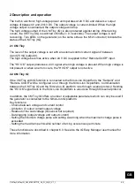
Page 49: ...ectly via the M12 connector or by using the CM Tiny external control kit The external control kit is a separate module that can be placed elsewhere in the machine and offers a range of options for providing an analogue setpoint for the output voltage See the CM Tiny external control kit manual for more information The CM Tiny IQ with IQ function can be used as described above in addition it can al...

Page 50: ...h voltage is not present or when an error occurs the HV OK output is not active 2 2 CM Tiny IQ If the CM Tiny with IQ function is connected to the Simco Ion IQ platform the Setpoint and Remote On Off will be configured on or through the Simco Ion IQ platform Communication between the CM Tiny IQ and the Simco Ion IQ platform runs through a serial protocol Sending the HV OK signal back to the Simco ...

Page 51: ...o high voltages can be dangerous for people with pacemakers An electric shock can cause a shock reaction even from high voltages that are safe to touch Warning Electrical installation and repairs must be carried out by a skilled electrical engineer with the relevant training and qualifications Disconnect the power supply before carrying out work on the unit The CM Tiny IQ must not be used in envir...

Page 52: ...12 connector 5 pin Output Output voltage 0 20 kV DC Output current Max 0 4 mA Environment Operating environment Industrial internal use Temperature 0 55 C Protection class IP54 Signalling HV OK output 24 V DC 3 V 50 mA max Serial using the Simco Ion IQ platform CM Tiny IQ only LED indications Green flashing quickly Start up Green flashing slowly Standby HV output inactive Orange Normal operation H...

Page 53: ... 5 pin M12 connector female A standard connection cable can be obtained from Simco Ion Netherlands or from the agent in your region See the spare parts list If the connection cable is to be fitted through a cable carrier please use the special flexible connection cable available from Simco Ion or another type that is suitable for this purpose If you have any problems or are unsure please contact S...

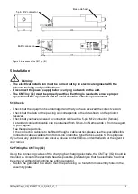
Page 54: ...igh voltage cable s to the electrode s bearing in mind that voltages of up to 20 kV can be generated Turn the locking screw right into the housing of the CM Tiny IQ Slide the electrode head onto the generator Manually turn the locking screw upwards until it is securely fastened in the electrode head Figure 3 electrode head on the CM Tiny IQ 5 3 1 Connection diagram CM Tiny analogue Figure 4 connec...

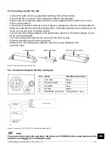
Page 55: ... The high voltage and the HV OK output are active If the CM Tiny is connected as seen in fig 4 standard analogue control the setpoint can be increased by connecting e g 7 5 mA 4 kV to the setpoint input Increasing the setpoint of a CM Tiny IQ connected to the Simco Ion IQ platform is described in chapter 6 3 6 2 Fine tuning the CM Tiny IQ Note The high voltage value must be set for optimum chargin...

Page 56: ...Alarm The status of the CM IQ Tiny is also displayed by the following symbols Hourglass CM Tiny IQ is starting up Pause CM Tiny IQ is in standby mode Play CM Tiny IQ is active Run The number of visible parameters depends on the selected user level on the Manager IQ Easy In this user manual the Expert user level is used The user level can be selected by going to the main screen of the manager and t...

Page 57: ...age output of the CM IQ Tiny the following conditions must be met The generator must be set to Run 6 3 1 Standby Run and Autorun A Setpoint has to be set 6 3 2 Control mode The Remote signal must be active or the generator must be set to continuous mode 6 3 3 Continuous and Remote mode The current output voltage and current can be read out with the parameters Output voltage and Output current Figu...

Page 58: ...aller current The charging current depends on the load of the generator and the possible fouling of the charging bar electrode The maximum output current can be set using the parameter Output current limit Only if the output current reaches the value of the Output current Limit parameter will the output voltage drop Operation CC Current Control mode Figure 13 operation CC mode If the CM Tiny IQ is...

Page 59: ...Easy I O connector on the I O connector For more information on the Remote On Off signal read the manual of the Manager IQ Easy 6 3 4 Setpoint threshold Remote mode only VC mode Setpoint threshold parameter Figs 9 and 14 serves to set the desired output voltage when the remote is in the OFF position This allows you to switch between two setpoints using the Remote On Off input signal By default Set...

Page 60: ...he parameter Paired sensor Figure 11 6 3 7 Arcing When arcing occurs between the high voltage output of the CM Tiny IQ and earth the generator will turn off briefly 0 3 seconds and a warning will be displayed on the screen of the Manager IQ Easy The number of arcings per minute is shown with the parameter Arcs per minute Figure 15 With the parameter Max arcs per minute the maximum number of arcing...

Page 61: ...d high voltage output temporarily inactive OR 2 Supply voltage too low HV output unchanged 3 HV OK output overloaded HS output active 4 Charging pulse too long HS output unchanged only CM Tiny IQ see also section 6 3 5 5 Eeprom read error HS output unchanged Red flashing quickly 5Hz only CM Tiny IQ No communication with the Simco Ion IQ platform HV output inactive See chapter 9 Faults to resolve p...

Page 62: ... screen will freeze and On hold will show on the display Clicking the screen again will display the current value 7 2 3 ActionLog tab In the ActionLog tab the changing status of the CM Tiny IQ is logged step by step This is indicated including the date and time the status change has occurred The main messages are HV OK the generator is turned on and is functioning properly HV NOT OK the generator ...

Page 63: ...ote Allow the CM Tiny IQ to dry completely before operating it again 8 2 Changing the electrode head The electrode head on the CM Tiny IQ is part of the charging electrode When changing a charging electrode the electrode head must also be changed See also figure 3 Turn the locking screw for the electrode head right into the housing of the CM Tiny IQ Pull the electrode head off the CM Tiny IQ Slide...

Page 64: ...12 cable connector LEDs do not light up orange keep flashing green High voltage set too low Increase output voltage by increasing setpoint 5 3 6 2 No signal on the Remote On Off input Connect 24 V DC 3 V to the Remote On Off input LEDs light up red Output voltage set too high arcing at the charging bar electrode Reduce output voltage by reducing setpoint or increasing distance to earth Short circu...

Page 65: ...up red Output voltage set too high arcing at the charging bar electrode Reduce output voltage by reducing setpoint or increasing distance to earth Short circuit between charging bar electrode or HV cable and earth Locate short circuit and eliminate LEDs are flashing red slow 1 Hz Generator overheated Make sure the ambient temperature is lower than 55 ºC Charging pulse too long Set the time for the...

Page 66: ...lifications CM Tiny IQ parts cannot be repaired To order parts see the spares list Request an RMA form for any returns by sending an email to service simco ion nl Pack the equipment properly and clearly state the reason for return 11 Disposal At the end of its service life do not throw the device away with the normal waste but hand it in at an official collection point By doing so you will help to...

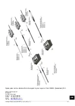
Page 67: ...CMTinyCMTinyIQ_UM_9752097710_NL_D_GB_F_V1_1 66 Spare parts ...

Page 68: ...7 GB Spare parts can be obtained from the agent in your region or from SIMCO Nederland B V SIMCO Nederland B V Postbus 71 NL 7240 AB Lochem Telefoon 31 0 573 288333 Telefax 31 0 573 257319 E mail general simco ion nl Internet http www simco ion nl ...

Page 69: ... uniquement CM Tiny IQ 777 6 3 1 Standy Run et Autorun 798 6 3 2 Point de consigne du courant et de la tension 799 6 3 3 Mode à distance et continu Remote Continuous 80 6 3 4 Setpoint threshold uniquement en mode à distance VC mode 80 6 3 5 Délai min max de la pulsation de charge uniquement en mode à distance 80 6 3 6 Tension Web 811 6 3 7 Formation d arcs 811 7 Contrôle du fonctionnement 822 7 1 ...

Page 70: ...ment et donner droit à sa garantie Les stipulations de garantie sont décrites dans les conditions générales de vente de SIMCO Nederland B V Description des symboles utilisés Les symboles suivants peuvent figurer dans la présente notice ou sur l équipement Avertissement Renvoie à des informations spécifiques destinées à éviter les blessures ou les dommages importants de l équipement ou de l environ...

Page 71: ...n du connecteur M12 ou bien au moyen du module externe de commande du CM Tiny Le kit de contrôle externe est un module séparé qui peut être installé ailleurs dans la machine et a des possibilités élargies pour donner un point de consigne analogique pour la tension de sortie Pour obtenir des renseignements complémentaires consultez la notice du module externe de commande du CM Tiny Le CM Tiny IQ av...

Page 72: ...uit la sortie HV OK ne sera plus active 2 2 CM Tiny IQ Quand le CM Tiny avec fonctionnalité IQ est raccordé à la plateforme Simco Ion IQ le point de consigne et le Remote On Off Commande à distance sont paramétrés ou via la plateforme Simco Ion La communication entre le CM Tiny IQ et la plateforme Simco Ion se déroule par un protocole en série Le retour d information du signal HV OK vers la platef...

Page 73: ... un danger pour les personnes portant un stimulateur cardiaque Un choc électrique peut déclencher une réaction de peur y compris si les hautes tensions ne présentent pas de danger de contact Avertissement L installation électrique et les réparations doivent être réalisées par un électrotechnicien professionnel qualifié En cas d intervention sur l appareil le mettre hors tension Le CM Tiny IQ ne pe...

Page 74: ...mA max En série par la plateforme Simco Ion IQ uniquement CM Tiny IQ Branchement Connecteur M12 5 broches Sortie Tension de sortie 0 20 kV DC Courant de sortie maxi 0 4 mA Environnement Environnement d utilisation Industrielle à l intérieur Température 0 55 C Classe de protection IP54 Indications Sortie HV OK 24 V DC 3 V 50 mA max En série par la plateforme Simco Ion IQ uniquement CM Tiny IQ Indic...

Page 75: ...rôle A la livraison contrôlez si l équipement n a pas été endommagé dans le transport et si sa version est bien celle commandée Vérifiez que les données de la fiche de colisage correspondent aux caractéristiques du produit livré Vérifiez qu un câble de raccordement muni d un connecteur M12 femelle à 5 broches est bien présent Le câble de raccordement standard est disponible auprès de SIMCO Nederla...

Page 76: ...chez le câble de raccordement comme indiqué en figure 4 analogue ou en figure 5 avec plate forme IQ Veillez à ce que les tiges électrodes chargeantes directement raccordées sans résistance en série ne soient pas en contact avec les objets mis à la terre ou bien trop près de ceux ci Reliez les câbles haute tension aux électrodes en gardant à l esprit que des tensions allant jusqu à 20 kV peuvent y ...

Page 77: ... Activez la tension d alimentation 24 V CC ou la plateforme Simco Ion IQ Les voyants situés sur le générateur émettent un clignotement vert rapide pendant le démarrage Un CM Tiny IQ contrôle pendant le démarrage si on utilise la plateforme IQ Simco Ion ou si une commande analogique est utilisée Après le démarrage les LED clignotent lentement en vert tant qu aucun point de consigne n est réglé pour...

Page 78: ...er Réglez le point de consigne de la tension de sortie environ 10 plus haut que la valeur optimale pour faire face aux fluctuations de processus Ne réglez pas sans nécessité des valeurs élevées pour prévenir l usure et la surcharge de la tige de l électrode chargeante 6 3 Fonctions IQ uniquement CM Tiny IQ Les fonctions IQ décrites dans ce chapitre sont uniquement disponibles sur le CM Tiny IQ en ...

Page 79: ...ciel Télécharger la dernière version du logiciel sur www simco ion fr software et suivant l instruction de Mise à niveau upgrade telle que décrite dans le manuel du Manager Les paramètres Device name et Machine position name peuvent être modifiés selon votre souhait Il peut être pratique de conserver un aperçu quand plusieurs CM Tiny sont montés sur une machine Illustration 8 CM IQ Tiny parameters...

Page 80: ... cette manière le générateur peut être mis en mode VC Voltage Control mode CC Current Control ou CLFB mode Closed Loop FeedBack le réglage du CM Tiny IQ par défaut en mode VC Illustration 8 Fonctionnement du mode VC Voltage Control Illustration 12 en mode VC Si le CM Tiny IQ est en mode VC la tension de sortie souhaitée doit être réglée avec le Setpoint voltage Le générateur maintiendra alors cons...

Page 81: ...nérateur ajoute constamment la tension de sortie pour obtenir la tension souhaitée de la bande La tension de sortie maximale du générateur peut être réglée avec le paramètre Limite de tension de sortie 6 3 3 Mode continu et distant Le CM Tiny IQ est par défaut en mode continu Figure 10 Lorsque le générateur est en mode continu la tension élevée sur la sortie sera active si les conditions suivantes...

Page 82: ...e peak Illustration 9 sont les valeurs mesurées sur le Web Pour mesurer ces valeurs une barre Sensor IQ Easy capteur est nécessaire Pour lire les valeurs du Sensor IQ Easy sur le CM Tiny IQ le capteur doit être relié au générateur avec le paramètre Paired sensor Illustration 11 6 3 7 Formation d arcs Quand un arc se produit entre la sortie haute tension du CM Tiny IQ et la terre le générateur va s...

Page 83: ...lent 1 Hz 1 Générateur en surcharge sortie haute tension temporairement inactive ou 2 Tension d alimentation trop faible sortie haute tension non modifiée 3 sortie HV OK surchargée sortie HS active 4 impulsion de charge trop longue sortie HS inchangée uniquement CM Tiny IQ voir aussi la section 6 3 5 5 Erreur de lecture Eeprom sortie HS inchangée Clignotement rouge rapide 5 Hz uniquement CM Tiny I...

Page 84: ...ctifs de la tige du capteur voir chapitre 6 3 6 Web voltage peak kV la charge maximale mesurée des segments actifs de la tige du capteur voir chapitre 6 3 6 7 2 2 Onglet Graphics Dasn l onglet Graphics le fonctionnement est présenté sous forme de graphique en fonction du temps Bleu la tension de sortie à la sortie haute tension kV Jaune le courant de sortie à la sortie haute tension mA Si on cliqu...

Page 85: ...délai intermédiaire entre l enregistrement est déterminé par le paramètre Logfile refresh time dans le Manager IQ Easy Voir le mode d emploi du Manager pour avoir de l information sur le fichier journal Illustration 17 DataLog tab Illustration 18 Maintenance tab 8 Entretien Avertissement En cas d intervention sur l appareil le mettre hors tension 8 1 Nettoyage du CM Tiny IQ Nettoyez le CM Tiny IQ ...

Page 86: ... raccordement Remplacer câble connecteur M12 Les voyants n émettent pas de lumière orange et continuent d émettre un clignotement vert La haute tension a été réglée à un niveau trop bas Augmenter la tension de sortie en rehaussant le point de consigne 5 3 6 2 Aucun signal à l entrée Remote On Off Commande à distance Appliquer une tension de 24 V CC 3 V à l entrée Remote On Off Commande à distance ...

Page 87: ...niveau trop haut étincelle arc près de la tige de l électrode chargeante Réduire la tension de sortie en diminuant le point de consigne ou bien en augmentant la distance par rapport à la terre Court circuit entre l électrode la tige chargeante ou câble haute tension et la terre Chercher et réparer le court circuit Les voyants émettent un clignotement rouge en 1Hz Surchauffe du générateur Contrôlez...

Page 88: ...réparables Pour la commande de pièces voir la liste de pièces de rechange Pour tout retour demandez un formulaire RMA par e mail à l adresse suivante service simco ion nl Emballer l équipement correctement et indiquer clairement la raison du retour 11 Mise au rebut A la fin de son cycle de vie ne pas jeter l équipement avec les déchets normaux mais s adresser à un centre de collecte agréé De cette...

Page 89: ...CMTinyCMTinyIQ_UM_9752097710_NL_D_GB_F_V1_1 88 Pièces de rechange ...

Page 90: ... pièces de rechange sont disponibles auprès de votre représentant local ou de SIMCO Nederland B V SIMCO Nederland B V Postbus 71 NL 7240 AB Lochem Telefoon 31 0 573 288333 Telefax 31 0 573 257319 E mail general simco ion nl Internet http www simco ion nl ...

Reviews: