


22
Section 4
Model 763A Gage Pressure Transmitter
Operation of the EGS Quick Disconnect Connector Assembly
IMPORTANT: Make sure that the O-ring and the connector sealing surface are clean
prior to performing the following steps.
To secure the connector in a locked position, perform the following steps:
1. Place the O-ring (Part No. 9A-C0001-1218R) onto the socket backshell
and seal it against the O-ring seating surface, stretching the O-ring slight-
ly to pass over the socket end. Do not roll the O-ring. The O-ring can be
applied dry or lubricated with a very thin coating of silicone lubricant
such as Parker "Super-O-Lube" or DC High Vacuum Grease (Part No.
9A-C0002-1003U). Lubricated O-rings should be rubbed with a clean
cloth prior to installation to remove excess lubricant.
2. Align the connector halves by positioning the "male D" plug into the
"female D" hole. When the two parts are aligned, they can be pushed
together until the O-ring is seated against the sealing surface on the con-
nector halves. When the connector halves are correctly aligned, the set
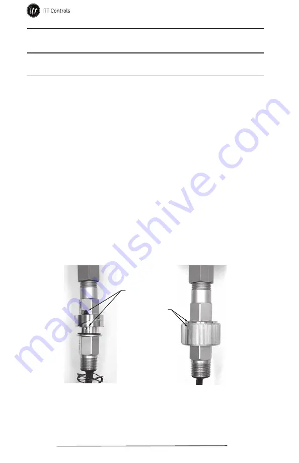
screws on the two halves will also be aligned (Figure 4.1, left).
3. Rotate the bayonet ring until its three pins are aligned with the three slots
on the pin backshell. Simultaneously push forward and twist the bayonet
ring clockwise (90 degrees) until the ring locks into place. The orange
dots on the bayonet ring should align with the orange slots on the mating
half (Figure 4.1, right). If they do not align, the connector is not locked
properly.
Set screws
Alignment marks
Figure 4.1—EGS quick disconnect connector assembly
To disconnect the connector, simultaneously push the bayonet ring towards
the socket backshell and twist it counter-clockwise 90 degrees). Pull the
mated halves apart to separate.
www.ittcontrols.com