background image

IB-5909 

INSTRUCTIONS  FOR 

TYPE  5HV-75,  5HV-150,  5HV-250  AND  5HV-'350 

METAL-CLAD  SWITCHGEAR 

5000  VOLT -1200,  2000  AND  3000  AMPERE 

INTRODUCTION 

Instructions for installation,  operation  and main­

tenance  of  type  SHV  metal-clad  switchgear  are 

furnished  with  each  shipment. 

These  instructions  should  be  read  carefully  and 

used  as  a  guide  during  installation  and  initial 

operation. 

File  these  instructions  in  a  readily  accessible 

place  together with drawings  and  descriptive  data 

of the switchgear. The use of these instructions will 

facilitate  proper  maintenance  of  the  equipment 

and  prolong its  life  and  usefulness. 

SCOPE  OF  INSTRUCTIONS 

These  instructions  are  general.  They  cover  re­

quirements  for  installation  as  applied  to  all  metal­

clad switchgear  of  the  5HV-75,  5HV-150,  5HV-250 
and  5HV-350  classification. 
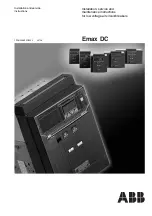
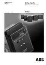
typical  example  is 

show  on the  front  cover. 

Specific information on particular applications is 

furnished  in  the  form  of job  drawings. 

1.  Front  view  showing  arrangement  of  relays 

and  instruments. 

2. 

Single  line  diagram  showing  power  con­

nections. 

3. 

Floor  plan  indicating  available  space  for 

power  and  control  conduits. 

4. 

Section  views  for  each  unit. 

5.  Special  construction  details. 

The  first  sheet  of  the  Bill  of  Material  indicates 

the  application  of  the  drawings. 

TRANSPORTATION 

Prior  to  shipment,  the  SHV  switchgear  under­

goes  careful  factory  inspection  and  crating.  Each 

crate  is  plainly  marked  at  convenient  places  with 

crate  number  and  position.  When  size  or  other 

reasons  make  it necessary to divide  the  equipment 

for  shipment,  the  unit  number  of  the  particular 

equipment  enclosed  is  also  marked  on  the  crate, 
along  with  its  weight.  The  circuit  breakers  are 

shipped  in  individual  crates. 

Immediately  upon  receipt  of  the  switchgear,  ex­

amine  for  any  damage  or  loss  sustained  during 

transportation.  Check  the  contents  again_st  the 

packing list before discarding any packing material. 

If  there  is  any  shortage  notify  the  nearest 1-T-E 

Circuit  Breaker  Company  representative  at  once. 

The 

1-T-E 

Circuit  Breaker  Company  is  not  re­

sponsible  for  damage  after  delivery 

of 

shipment 

to  the  carrier.  However,  if the  company  is notified 

of  such  claims,  it  will  furnish  forms  to  facilitate 
securing  any  adjustments.  If  damage  to  the  ship­

ment  indicates  rough  handling,  claim  for  damage 

should  be  filed  at  once  with  the  carrier  and  the 

I-T-E  Circuit  Breaker  Company  promptly  notified. 

The switchgear housings are crated and shipped 

in  groups  of  one  to  six  units.  Each  group  is  pro­

vided  with  heavy  wooden  skids.  The  remainder  is 

crated  for  protection.  Unloading  and  handling  at 

the  site  is  usually  done  by  placing  rollers  under 

the  skid.  To  avoid distortion to the switchgear,  any 

force  to  move  the  structures  should  be  applied 

to the  skid  by means of crowbar,  block  and  tackle, 

crane,  etc. 

STORAGE 

Remove  crating  from  the  switchgear  units,  but 

leave  each  group  on  its  skid  for  subsequent  mov­
ing.  Uncrate  circuit  breakers  and  accessories. 

Observe  the  following  precautions: 

1.  Check  for  missing  or  damaged  parts. 

2.  Store  in  clean,  dry  place. 

3.  Cover  parts  susceptible  to rust  with heavy  oil 

or grease. 

4. 

Cover  with  heavy  wrapping  paper  to  keep 

dirt  or  dripping  water  from entering.  Dirt  or  mois­

ture may foul working parts or  deteriorate contacts 

and  insulation. 

5.  If  the  switchboard  is  to  be  stored  for  any 

length  of  time,  or  in  any  place  where  dampness 

may  be  present,  then  heaters  should  be  ..:sed  to 

keep  the  switchboard  dry  until it  is placed  in  serv­

ice.  When  outdoor  switchboards  equipped  with 

heaters  are  stored,  the  power  source  for  the 

heaters  should  be  brought  to  the  load  terminals of 

the  ET  thermal  circuit  breaker  or  cutout  device 

which  controls  the  heater  circuits. 

UNLOADING  AND  HANDLING 

The  following  is  a  recommended  method  for 

unloading  and  handling  type  5HV  metal-clad 

switchgear  housings. 

INDOOR  INSTALLATION 

1.  Prior  to  uncrating,  the  switchgear  should  be 

moved near installation site.  This operation may be 
completed by raising switchgear shipping skid with 
track jacks  to allow rollers to be placed under skid. 

2. 

After  switchgear  housings  have  been  mo"Yed 

·to  site,  uncrate 

a.mi 

remove  lag  screws 

located 

• 

www 

. ElectricalPartManuals 

. com 

Summary of Contents for 5HV-150

Page 1: ...PE 5HV 75 5HV 150 5HV 250 AND 5HV 350 METAL CLAD SWITCHGEAR 1 t i t I 5000 VOLT 1200 2000 AND 3000 AMPERE i 1 i x rt i y t l l 1 T E CIRCUIT BREAKER COMPANY PHILADELPHIA 30 PENNSYLVANIA PRINTED IN U S A 7 59 2M w w w E l e c t r i c a l P a r t M a n u a l s c o m ...

Page 2: ... Inspection 7 STANDARD CONSTRUCTION Shutters 7 Bus Insulation 8 Primary Disconnecting Device 8 Secondary Disconnecting Devices 8 Ground Bus and Contacts 9 Control Wires 9 5HV 75 5HV 150 AND 5HV 250 CIRCUIT BREAKERS General 9 Installation and Removing from Housing 10 SHV 350 CIRCUIT BREAKER Installation and Removing from Housing 13 HOW TO PUT THE SWITCHGEAR IN SERVICE General 14 Safety Precautions ...

Page 3: ... once The 1 T E Circuit Breaker Company is not re sponsible for damage after delivery of shipment to the carrier However if the company is notified of such claims it will furnish forms to facilitate securing any adjustments If damage to the ship ment indicates rough handling claim for damage should be filed at once with the carrier and the I T E Circuit Breaker Company promptly notified The switch...

Page 4: ... Switchgear Raised Rollers and Channels in Place Prior to Lateral Moving Fig 2 Switchgear Lowered on Rollers Prior to Moving Onto Track Timber Fig 4 Method oF Applying Rollers as Switchgear Progresses Onto Track Timber Fig 6 Jaclcs Removed and Switchgear Ready For Lateral Moving V _ ii J ff jFfft tl _ w w w E l e c t r i c a l P a r t M a n u a l s c o m ...

Page 5: ... the lower flange of the sill be shimmed to proper height Temporary bolts should be inserted in all tapped holes while grouting to prevent filling or damage to the threads Where necessary power and secondary con trol conduits should be installed before the in stallation of the housings Available space for the conduits is given on the floor plan accompanying each order These conduits should not ext...

Page 6: ...f the pothead with wiping sleeve the lead sheath should extend into the pot head for one inch minimum bell over the end of 6 the sheath and add a stress relief cone if required Clean the sheath about three inches beyond the end of the cone and apply stearine flux to end of the cone and the sheatlt Wipe the joint in the usual manner On inverted potheads the lead sheath should be extended down into ...

Page 7: ...AS POTENTIAL IB 5909 TRANSFORMERS ARE CONNECTED DURING THE TESTS 4 Check continuity of all circuits A great deal of this work can be done after the circuit breakers are installed by energizing the control source and operating the equipment with the main circuit dead Indicating instruments check the continuity of current transformer and potential transformer circuits after the main circuit is energ...

Page 8: ...ing Device fingers tends to increase the contact pressure dur ing a short circuit All contact finger springs are outside the current path The stationary disconnecting device is rigidly mounted in an insulating molding of cylindrical shape located within the main bus housing See Fig 8 For the SHV 350 housing the disconnecting device is similar but mounted in a molding of rectangular outline SECONDA...

Page 9: ...ERATING positions Inserting the crank in the center hole and turning to the limit in the counter clockwise direction moves the pointer and racking bar from the connected OPERATING position out to the RACKED OUT position Turn ing the crank to the limit in the clockwise direction moves the pointer and the racking bar on the breaker into the connected position The maintenance handle is used to close ...

Page 10: ...I w w w E l e c t r i c a l P a r t M a n u a l s c o m ...

Page 11: ... the drawout handle back the breaker into the housing so that the guide bar on the breaker enters the guide slot in the housing Push breaker toward rear until breaker reaches the floor stop which latches it in the TEST position IO Fig 13 5HV 150 and 5HV 250 Racking and Indicator Assembly Unlock Position If it is desired to test the breaker for operation electrically and manually before putting it ...

Page 12: ...w w w E l e c t r i c a l P a r t M a n u a l s c o m ...

Page 13: ...ed OPERATING position Fig 18 REMOVING 5HV 150 AND 5HV 250 BREAKER FROM HOUSING 1 Trip breaker by means of the control switch on front of housing IB 5909 Fig 15 Manually Closing Circuit Breaker While in Test Position 2 Open door insert crank and rack breaker Fig 17 to RACKED OUT position as indicated by pointer on breaker nameplate If it is desired to remove the breaker completely from the housing ...

Page 14: ...w w w E l e c t r i c a l P a r t M a n u a l s c o m ...

Page 15: ...w w w E l e c t r i c a l P a r t M a n u a l s c o m ...

Page 16: ...r fo Raclced Oul Position 1 t Fig 18 Circuit Brealcer in Fully Connected Position 12 Fig 17 Racking in Circuit Brealcer to Fully Conneded Position i Fig 19 Pu ling Out Circuit Breaker from Housing w w w E l e c t r i c a l P a r t M a n u a l s c o m ...

Page 17: ...ease lever and rack the breaker to the OPERATING position as shown in Fig 21 IB 5909 Fig 21 Raclcing in SHV 350 Breaker to Fully Connected Position REMOVING 5HV 350 BREAKER FROM HOUSING 1 Trip the breaker by means of the control switch 2 Open the compartment door insert the rack ing rod push down on the racking release lever and rack the circuit breaker out to the rEST position as indicated by the...

Page 18: ... J w w w E l e c t r i c a l P a r t M a n u a l s c o m ...

Page 19: ...ave been placed in the test position Close all doors to the switchgear as a safety measure Those breakers necessary to energize the main bus should be moved to the connected position and closed Observe undervoltage relays or other devices that should function properly when the main bus is energized Next move each circuit breaker in turn to the connected position and close Method explained under IN...

Page 20: ...w w w E l e c t r i c a l P a r t M a n u a l s c o m ...

Reviews: