Green Heating Technology
44
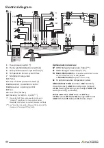
Electrical diagram
1 2
4
3
PE
N
L
M0101
M0102
M0901
M0900
M0904
NC
NO
NC
NO
3
4
2
1
YG
BN
BU
3 DHW
2 CO
M
1 HE
A
WH
BK BK
RD
BU BU
BK
BK OG
OG
VT
VT
GN
GN
BU
BU
WH
WH
BU
BU
WH
WH
RD
BN
YG
BU
BN BU
BU BN
BK
41
7
1
6
5
12
13.2
13.1
10
19
003383 01
L N
SE
TA
4
SP
ST
42
(SP)
(ST)
1
Flue pressure switch (*)
4
Flame ignition/detection electrode
5
Safety thermostat on system flow (*)
6
Temperature Sensor, system flow
7
Motorized 3-way valve
10
Pump
12
Loss of water pressure switch (*)
13.1
Gas valve - modulation control
13.2
Gas valve - opening control
19
Fan
41
Fuse F2A (2A fast)
42
Resistor, 2.2 kOhm - 1/2W (**)
(*)
the contacts of these components are shown in
"standard" conditions (i.e. temperature below
threshold, cold system, no system pressure, no flow)
(**)
see
"Electrical connection between the boiler and the
storage unit" on page 21 for details.
Optional external devices:
SP
DHW Storage temperature Probe (**)
ST
DHW Storage Thermostat (*) (**)
TA Room thermostat:
(or Chronothermostat) SELV simple
contact. Closed contact = heating request.
or
Remote control
(
original
accessory only)
SE
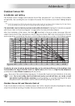
To optional outdoor temperature sensor
Abbreviations:
COM
Common
●
NC
Normally
closed (contact)
●
NO
Normally open (contact)
●
HEA
Heating (diverting command)
●
DHW
Hot
water (diverting command)
Colours:
BK
Black
●
BN
Brown
●
BU
Blue
●
GN
Green
●
RD
Red
●
OG
Orange
●
VT
Violet
●
WH
White
●
YE
Yellow
●
YG
Yellow-Green


