Green Heating Technology
22
Flue systems
General indications
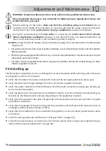
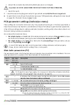
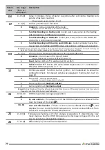
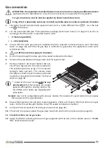
To ensure the functionality and the efficiency of the appliance it is necessary to foresee,
for the hori-
zontal ducts
of air inlet and flue outlet, a slope of 2÷5% downwards
from the boiler to the outside
(see
diagram).
In the case of
vertical flue
outlet duct, to avoid condensation reflux in the sealed chamber,
it is neces-
sary to use a suitable condensate collection kit
�
Air inlet and flue outlet terminals should be protected by suitable approved flue accessories, to avoid
environmental elements penetration.
Don't lean the flue pipe into the chimney, but stop it before the inner surface of the chimney. The axis
of the flue pipe must intersect the axis of the chimney or of the flue duct.
00008 ENG 00
Eventual
coaxial
inlet
Horizontal flue outlet
Vercal flue outlet
2% ÷ 5%
Condensate
collecon
device
Flue duct
or chimney
NO
NO
YES
Carefully follow the prescriptions by the National and Local Regulation in force.
Respect the minimum and maximum flue system length (refer to "Flue system types" on page 23).
Reducer for short systems
In case of short air inlet and flue outlet systems, to achieve the correct combustion, the installation of
a suitable flue diameter reducer could be necessary. The reducer that fits most cases is supplied with
the boiler. In a few particular cases, it could be necessary a different reducer, optional, to be ordered by
mentioning its inner diameter or the relevant spare part number (see technical literature). Indications
about the use of the reducer (and the relevant diameter, for the optional reducer), on the basis of the
flue system type and length, are contained in the paragraph "Flue system types" on page 23
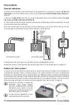
Referring to the tables, calculate the
equivalent linear length consider-
ing every additional bend installed
(exclude the ones shown in the dia-
grams) and, if required, install the re-
ducer
D
as shown in the figure.
Comply with the regulation in force
when installing the flue systems.

