


Green Heating Technology
36
f
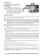
unscrew the 4 nuts
1
which fix the burner group
13
(composed of fan, hose and burner) to the pri
-
mary exchanger. Remove the burner group;
Do not disassemble the burner group and do not dismount the ceramic fibre plate from the bot
-
tom of the exchanger.
f
check the integrity of the insulating coverings inside the combustion chamber;
f
on the burner cover, check the integrity of the fireproof fibre gasket and of the silicone rubber one;
f
check that the burner do not present deposits, foulings or excessive oxidations and that all the holes
are free;
f
clean softly the burner electrodes, avoiding to bend it or to move it;
f
clean the cylinder of the burner ONLY IF IT IS NECESSARY and only DRY, through a NOT METALLIC
brush, with movements on the burner’s axis, from cover outwards;
Do not damage the insulating coverings inside the combustion chamber and don't deform the
holes of the burner. If the burner works correctly, it will be of black colour but clean or in any
case with few deposits, not scaled and easy to remove.
f
slip off the outlet condense pipe
10
from the connection on the primary exchanger. It's advisable to
plug on the connection a suitable pipe, to divert outside the boiler (and especially out of the conden
-
sate syphon) the dust that detaches from the primary exchanger during the cleaning;
f
to clean the primary exchanger:
•
prior to brushing the exchanger's coils, carefully remove, by a powerful vacuum cleaner, the solid
residuals of combustion;
don't use air jets;
•
then clean the primary exchanger coils by a NOT METALLIC brush and remove the residuals again
by using the vacuum cleaner;
f
locate the lower cap
8
of the siphon (where you can access from the lower side of the boiler, behind
the returned connector of the system), put a collector for liquids under it. Unscrew the cap. Let the
siphon empty itself. Inside the cover a layer of residual could be present (max 1÷2mm): remove it;
Remark:
an excessive quantity of residual is an indicator of malfunctioning or in any case it is not a
normal situation. Locate the reasons and solve the problem, so remove the siphon unscrewing
the superior and lateral connectors, and the screw of its support bracket. Accurately clean the
siphon and be sure that its condense inlet pipe
10
and condense outlet pipe
7
are clean and not
obstructed.
f
Reassemble all the components in the backwards order and opposite sense and check the combus-
tion.
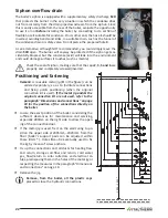
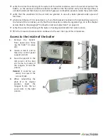
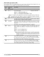
PCB parameters settings (technician menu)
These settings are reserved to Technician only. The procedure how the get in the boiler parameters is
known by technician only thanks to a combination of steps which allows to gain the boiler parameters.
A few of these settings allow to optimise and tailor the boiler working, while a few others allow to set
the boiler during maintenance operation.
The digits under the symbol
on the left side of the display indicates the number of the parameter.
Instead, the number on the right side (usually under the symbol
or by the shown number placed
at the bottom side of the display) is referred to the parameter value (setting) the parameter is set on.
In case of PCB replacing, check all of the parameter settings otherwise set them properly.
Please, do not modify any firm setting if this is not required.


