InstructIon manual
2018-05-07
T
he
reference
in
surface
TreaTmenT
International
Surface
Technologies
i s t s u r f a c e . c o m
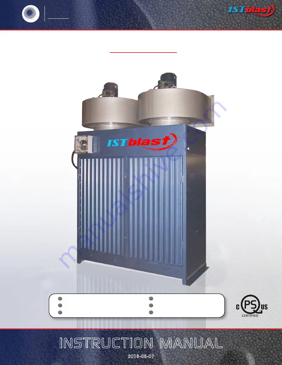
DUST COLLECTOR
TYPE AIRWALL 16000
Warranty
Safety Operation
Service Parts Accessory Information Registration Form
Page 1: ...nual 2018 05 07 The reference in surface treatment International Surface Technologies istsurface com DUST COLLECTOR TYPE AIRWALL 16000 Warranty Safety Operation Service Parts Accessory Information Reg...
Page 2: ...electrical details Parts list 21 Parts list Cont d 22 timer controller system 23 Series DCT1000 Dust Collector Timer Controller 24 Specifications Installation and Operating Instructions 24 Series DCT...
Page 3: ...ouse 4 Check the equipment zx and compare it with the parts you have received If any parts are missing contact the supplier you purchased the equipment from Before operating the ISTblast SANDBLASTING...
Page 4: ...e combined by the user in a variety of ways for purposes determined solely by the user No representations are intended or made as to the suitability or engineering balance of the combination of produc...
Page 5: ...nce of drugs DO NOT OVERREACH Keep proper footing and balance at all times BEFORE CONNECTING THE UNIT be sure the power is the same as that specified on the nameplate of the Sand Blasting Cabinet With...
Page 6: ...The differential pressure gauge shows the pressure difference between the dust side and clean side of the cartridges The led indicator helps determine the proper pulse pressure and timer off time set...
Page 7: ...und to the grounding lug located on the rear wall of the dust collector Compressed Air Connections NOTE For maximum filter life and efficiency the pulse air source should be 30 relative humidity or le...
Page 8: ...e pressure regulator located on the pulse manifold inlet adjust pulse pressure Set initial pressure at 70 psi Pulse Sequence Control Panel Your dust collector is equipped with an automatic cartridges...
Page 9: ...led locked out and tagged out Failure to do so could result in death or serious injury from electrical shock unintentional actuation of a component or from the venting of trapped compressed air WARNIN...
Page 10: ...are to be removed by blasting and obtain a Materials Safety Data Sheet for the blast media Collector Not Pulsing Check the manifold pressure gauge If the reading is low check the regulator adjustment...
Page 11: ...dust Check and clean Make sure the tubing has not been inserted so far into the tube connection that it blocks the tube ends The in line dust filter may be blocked Clean or replace Snubbed fittings b...
Page 12: ...The reference in surface treatment International Surface Technologies istsurface com 12 AW16000 Instruction Manual A 1 1 2 electrical panel see fig G front view...
Page 13: ...The reference in surface treatment International Surface Technologies istsurface com 13 AW16000 Instruction Manual Right side view B 10 4 5 9 3 2 1 7 8 6...
Page 14: ...The reference in surface treatment International Surface Technologies istsurface com 14 AW16000 Instruction Manual left side view C 1...
Page 15: ...The reference in surface treatment International Surface Technologies istsurface com 15 AW16000 Instruction Manual rear view D 1...
Page 16: ...The reference in surface treatment International Surface Technologies istsurface com 16 AW16000 Instruction Manual top interior view Top Interior E 2 3 1...
Page 17: ...The reference in surface treatment International Surface Technologies istsurface com 17 AW16000 Instruction Manual electrical details Connectors cdes Panel F 1 2 5 6 4 8 7 3 11 10 9 2 12...
Page 18: ...PN AIR INLET STOCK DESCRIPTION 1 NPN FOAM GASKET STOCK DESCRIPTION 1 618054 STARTER WITH BUTTON 2 617053 STARTER 3 616572 ELECTRIC CABLE 14 3 4 608568 SOLENOID 5 616535 LIQUID TIGHT CABLE 3 8 STOCK DE...
Page 19: ...ETHANE HOSE 1 4 3 324561 PUSH IN 1 8 NPT X 1 4 4 N PN ON BUTTON 5 NPN OFF BUTTON 6 616741 STRAIN RELIEF 2522 STOCK DESCRIPTION 7 616770 CONNECTOR 3 8 8 616742 STRAIN RELIEF 2525 9 908704 PRESSURE MODU...
Page 20: ...n surface treatment International Surface Technologies istsurface com 20 AW16000 Instruction Manual Timer Controller ststem DCP 100 Pressure module 908704 DCT 100 Static pressure indicator DCT 1000 Se...
Page 21: ...or continuous cleaning applications Continuous cleaning applications do not require external inputs and can be used for time based on demand cleaning through use of the cycle delay feature For on dema...
Page 22: ...oved under any circumstances For ease of installation and maintenance the connectors and fuse have been left unprotected The open frame design of the DCT1000 will require an enclosure that meets appro...
Page 23: ...on and L2 are internally connected Switches connected to the control inputs at the top of the board must be isolated contacts connected only to the relevant terminal and to the common terminals The fo...
Page 24: ...ough use of an external normally open switch 1 2 4 Connecting Multiple Timer Boards Both master controller boards and slave boards can have up to a maximum of 22 channels each The system may be expand...
Page 25: ...able for different applications Starting with the most basic mode it is capable of operating in a continuous cleaning cycle This can be initiated by either placing a jumper between the high limit inpu...
Page 26: ...s to secure the module In normal operation these are not required since the latching tabs are sufficient to secure the module even in a high vibration environment However if the unit is to be shipped...
Page 27: ...rol panel or by an external switch connected between the alarm reset terminal and one of the common terminals The alarm reset will only operate if the pressure module is installed and the pressure has...
Page 28: ...When first selected the display will flash the last output available in the system With single board installations this will be the number of channels installed typically 6 10 or 22 This value becomes...
Page 29: ...Setup is identical to the High and Low Limit Setup The Low Alarm default is 0 The upper settable value is the full scale pressure of the pressure module and the lower limit is zero Pressing SELECT wi...
Page 30: ...ind that each channel is provided with an LED that is illuminated when the triac switch is on This allows a visual correlation between the channel being pulsed and the operation of the solenoid 3 4 Co...
Page 31: ...only appear when the master controller is used in conjunction with a slave board Make sure the control cable used in the daisy chain interface is properly shielded from noise Err 4 The master controll...
Page 32: ...age circuitry Demand Cycle Mode A process in which the run mode is enabled through the on board pressure module or an external switch such as the Dwyer Photohelic Euro Connector A caged connection use...
Page 33: ...ER sOLeNOiDS Line input MASTER CONTROLLER INPUT MUST NOT BE CONNECTED normally open contacts CONNECTIONS 4 20mA Series DCP100A 200A Pressure Modules Specifications Installation Operating Instructions...
Page 34: ...20 mA circuit is isolated from groundand other signals The alarm relay contactsare isolated normally open contacts Pressure connections may be made to thestepped hose barbs with either 1 8 or3 16 I D...
Page 35: ...to the desired setting Pressing bothUp and Down buttons simultaneously andholding for about four seconds will restore the factory default 2 3 High Alarm Setup The operation of the High Alarm Setup is...
Page 36: ...LUSIVE PROPERTY OF ISTBLAST INFORMATIONS CONTAIN HEREIN CAN BE USED ONLY WHEN SPECIFICALLY AUTHORIZED BY CHEMCHAMP POSSESSION OF THIS DRAWING DOES NOT AUTHORIZED USE FOR TRANSMISSION TO ANY DROITS EXC...
Page 37: ...N BE USED ONLY WHEN SPECIFICALLY AUTHORIZED BY CHEMCHAMP POSSESSION OF THIS DRAWING DOES NOT AUTHORIZED USE FOR TRANSMISSION TO ANY OTHER ORGANIZATION DROITS EXCLUSIFS C e dessin est L A P R O P R I T...
Page 38: ...t does not disclose any defect in material or workmanship repairs will be made at a reasonable charge which charges may include the costs of parts labor and transportation THIS WARRANTY IS EXCLUSIVE A...
Page 39: ...on Manual WARRANTY INFORMATION TECHNICAL ASSISTANCE www istsurface com Tel 1 877 629 8202 450 963 4400 Fax 450 963 5122 For more information pricing or technical support contact your local IST distrib...
Page 40: ...__ __ __ TEL NUMBER __ __ __ __ __ __ __ __ __ __ FAX NUMBER __ __ __ __ __ __ __ __ __ __ PURCHASE FROM __ __ __ __ __ __ __ __ __ __ __ __ __ __ __ __ __ __ __ __ __ __ __ __ __ __ __ DATE OF PURCHA...