background image


19 

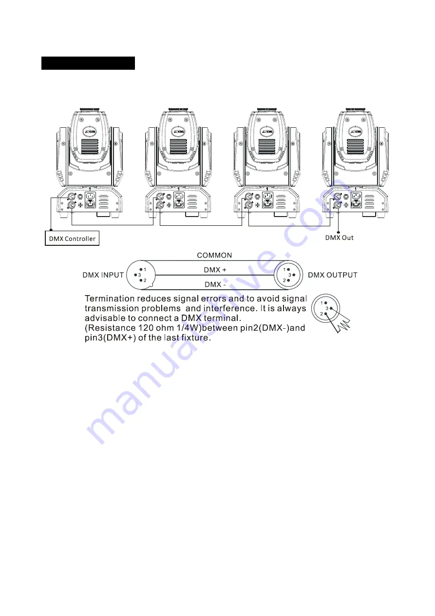
6.   DMX   Connection       


Unit   1                                                    Unit   2                                                            Unit   3                                                            Unit   4   


1.


If   you   using   a   controller   with   a   5   pin   DMX   output,   you   need   to   use   a   5   to   3   pin   adapter-­‐cable   

2.


The   last   units   DMX   cable   has   to   be   terminated   with   a   120   ohm   1/4W   resistor   between   pin   

2(DMX-­‐)   and   pin   3(DMX+)   of   a   3-­‐pin   XLR-­‐plug   and   plug   it   in   the   DMX-­‐output   of   the   last   unit.   

3.


Connect   the   units   together   in   a   `daisy   chain`   by   using   a   DMX   cable   from   the   output   of   the   unit   

to    the    input    of    the    next    unit.    The    cable    can    not    branched    or    split    to    a    `Y`    cable.    The    DMX   

output   and   input   connectors   are   a   “pass-­‐through”   type   to   maintain   the   DMX   circuit   even   if   

one   of   the   units   power   is   disconnected.   

4.


Each   fixture   unit   needs   to   have   an   address   set   to   receive   the   data   sent   by   the   controller.   The   

address   number   are   between   1-­‐512       

5.


The   end   of   the   DMX   512   line   system   should   be   terminated   to   reduce   signal   errors.   

Summary of Contents for iMove 150

Page 1: ...Order Code ISIM29 User Manual Please read the instructions carefully before use...

Page 2: ...verview 4 3 2 Gobo Wheel 6 3 3 Main Functions 6 3 4 Home Position Adjustment 12 4 How to Control the Unit 13 4 1 Master Slave Built In Preprogrammed Function 13 4 2 CA 8 Easy Controller 14 4 3 DMX Con...

Page 3: ...Make sure there are no flammable materials close to the unit while operating as they may be a fire hazard Use safety cables when installing this unit DO NOT handle the unit with its head only always...

Page 4: ...cable that can hold 12 times of the weight of the fixture when installing The equipment must be installed by professionals It must be installed in a place where is out of the reach of people and no on...

Page 5: ...1 LED DMX On DMX input present MASTER On Master Mode SLAVE On Slave Mode SOUND Flashing Sound activation 2 Button MENU To select the programming functions DOWN To go backward in the selected function...

Page 6: ...DMX OUT DMX 512 link use a 3 pin DMX cable to link the next unit and the output DMX signal 5 Only For Remote Control Connects to optional CA 8 controller to control the unit in Stand by Function and S...

Page 7: ...d the display will blink Use the DOWN UP buttons to change the mode Once the required mode has been selected press the ENTER button to setup To go back to the functions without any changes press the M...

Page 8: ...XTURE HOURS MENU SOFTWARE VERSION LED DISPLAY OFF LED DISPLAY ON DISPLAY INVERSION NORMAL SLAVE MODE BLACKOUT MODE SOUND MODE TEST SOUND SENSE RESET NORMAL PAN INVERSION NORMAL TILT INVERSION TEMPERAT...

Page 9: ...n Press and hold the MENU button for about one second or wait for one minute to exit the menu mode SHOW MODE To select press the ENTER button to show the SHOW MODE on the display Use the DOWN UP butto...

Page 10: ...U button again Press and hold the MENU button for about one second or wait for 7 seconds to exit the menu mode SOUND MODE To select press the ENTER button to show the SOUND MODE on the display Use the...

Page 11: ...nu mode Display normal mode for floor standing fixture Display inversion mode for ceiling or truss mounting LED DISPLAY To select press the ENTER button to show the LED DISPLAY on the display Use the...

Page 12: ...u mode TEMPERATURE To select press the ENTER button to show the TEMPERATURE on the display To go back to the functions without any changes press the MENU button again Press and hold the MENU button fo...

Page 13: ...alue from 127 to 127 press the ENTER button to store Press the MENU button to exit Tilt home position adjustment To select press the ENTER button to show the TILT OFFSET on the display Use the DOWN an...

Page 14: ...some noises for about 20 seconds After that the unit will be ready to receive a DMX signal or run the built in programs 4 1 Master Slave Built In Pre programmed Function By linking the units in maste...

Page 15: ...Strobe 2 Async strobe 3 Sound Strobe Show 1 4 1 Press to select colour 2 Hold to select gobo Mode Sound LED OFF Show LED Slow Blinking LED ON 4 3 DMX Controller If you are using a universal DMX contro...

Page 16: ...5 Open 016 131 Strobe Slow to Fast 132 139 Open 140 181 Slow Open Fast Close 182 189 Open 190 231 Fast Open Slow Close 232 239 Open 240 247 Random Strobe 248 255 Open 4 COLOUR 000 007 white 008 014 Co...

Page 17: ...shaking 111 119 Gobo5 shaking 120 127 Gobo6 shaking 128 189 Clockwise Gobo Scroll Fast to Slow 190 193 Stop 194 255 Counter Clockwise Gobo Scroll Slow to Fast 6 GOBO ROTATION 000 009 Stop 010 119 Cloc...

Page 18: ...139 Open 140 181 Slow Open Fast Close 182 189 Open 190 231 Fast Open Slow Close 232 239 Open 240 247 Random Strobe 248 255 Open 6 COLOUR 000 007 white 008 014 Colour1 015 021 Colour2 022 028 Colour3 0...

Page 19: ...e Gobo Scroll Fast to Slow 190 193 Stop 194 255 Counter Clockwise Gobo Scroll Slow to Fast 8 GOBO ROTATION 000 009 Stop 010 119 Clockwise Rotation fast to slow 120 134 Stop 135 245 Clockwise Rotation...

Page 20: ...3 Connect the units together in a daisy chain by using a DMX cable from the output of the unit to the input of the next unit The cable can not branched or split to a Y cable The DMX output and input c...

Page 21: ...D is on and no response to the controller check the address settings and DMX polarity 3 Try another DMX controller C Some fixtures don t respond to the CA 8 Easy controller 1 You may have a break in t...

Page 22: ...ends on the environment in which the fixture operates moist smoky or particularly dirty surrounding can cause greater accumulation of dirt on the fixture Clean with a soft cloth using normal glass cle...

Page 23: ...h the provision of the Electromagnetic Compatibility EMC Directive 89 336 EEC EN55103 1 2009 EN55103 2 2009 EN62471 2008 EN61000 3 2 2006 A1 2009 A2 2009 EN61000 3 3 2008 Harmonized Standard EN 60598...

Page 24: ...23 Innovation Quality Performance...

Reviews: