background image

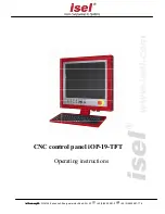
CNC control panel iOP-19-TFT 

Page - 9 


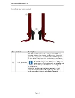
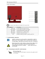
Control computer control elements 


No. 

Element 

Description 

11 

USB connections 

The iOP-19-TFT is fitted with an integrated USB hub. This 
provides integrated touch screen connection. The three USB 
ports allow equipment such as USB sticks, a USB keypad, a 
WIBU dongle or an external CD ROM drive to be connected.  


The USB hub is provided with its own +24V power 
supply (active USB hub). Power is fed to the hub via 
the machinery control element connecting cable 

(see Chapter 3). 
If the CNC control panel has been connected to an isel 
computer not fitted with a +24V supply (e.g. iPC15), the 
touch screen and USB ports will remain inoperative.   

Summary of Contents for iOP-19-TFT

Page 1: ... isel Germany AG isel Germany AG D 36124 Eichenzell Buergermeister CNC control panel iOP Operating 36124 Eichenzell Buergermeister Ebert Str 40 49 0 6659 981 0 CNC control panel iOP 19 TFT Operating instructions 49 0 6659 981 776 TFT ...

Page 2: ...b due to the presence of high voltage electrical circuits Failure to observe the danger can result in severe injury or death Attention This symbol means important instructions are being given Failure to observe the instructions may result in equipment malfunction or damage to machinery Information This symbol means important information or advice is being given Complying with safety information Pr...

Page 3: ...AG isel Germany AG isel Germany AG isel Germany AG machines and controllers are CE compliant and labelled accordingly This equipment must not be operated until the CE safety guidelines applying to all associated machinery parts and components have been fully complied with isel Germany AG isel Germany AG isel Germany AG isel Germany AG accepts no liability for damage to equipment or malfunction whe...

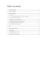
Page 4: ...h screen 6 2 2 Description of control elements 7 3 Connections of the control elements 10 3 1 Connection of the controls for the control PC 10 3 2 Power supply for the CNC control panel 11 3 3 Connection of machine controls 12 4 Faults 13 5 Service and maintenance 13 6 Technical Data 14 6 1 Technical Data iOP 19 TFT 14 7 EC Declaration of Conformity 15 ...

Page 5: ... series control computer Equipment operations must only be carried out by authorised qualified personnel and in full compliance with electrical industry regulations and safety standards Ensure the equipment is fully disconnected from the mains supply before opening the cover and carrying out any electrical installation work Ensure there is sufficient ventilation in the immediate vicinity of the mo...

Page 6: ...ard optional robust aluminium housing Aluminium stainless steel look front panel Simple assembly using VESA 100 100 mounting Integrated machinery control elements 19 TFT with touch screen Max resolution 1280 x 1024 pixels 3 USB connections pull out connecting cable compatible with isel control computer Stand Swivel arm for connection to PS profile Simple keyboard mouse storage compartment Superior...

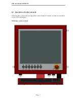
Page 7: ...ontrol panel iOP 19 TFT Page 7 2 2 Description of control elements In the standard version the most important control elements buttons switches are mounted on the CNC control panel Machinery control elements ...

Page 8: ...e COVER button is illuminated the cover can be opened 7 Operating Mode Selector Switch This key switch allows the unit to be switched between the Automatic Operation and Set Up modes In Automatic Operation the cover or door of the machine can only be opened when the shafts are not in motion and the cutting spindle has been switched off In the Set Up mode the cover or door of the machine can only b...

Page 9: ... ports allow equipment such as USB sticks a USB keypad a WIBU dongle or an external CD ROM drive to be connected The USB hub is provided with its own 24V power supply active USB hub Power is fed to the hub via the machinery control element connecting cable see Chapter 3 If the CNC control panel has been connected to an isel computer not fitted with a 24V supply e g iPC15 the touch screen and USB p...

Page 10: ...ameter of at least 2 5mm2 screened cable or 4mm2 un screened cable and connected between the iOP 19 terminal and the safety bus bar of your machine 3 1 Connecting the control PC control elements DVI connecting cable This cable is fitted with a DVI plug for connection to the graphic card of your computer No Element Description 1 Menu top Use the menu to navigate to the top 2 Menu bottom Use the men...

Page 11: ...CNC control panel the indicator LEDs into the front panel of the equipment cover and the TFT power supply into the socket provided on the control computer Insert the plug into the D sub socket provided on the control computer in the switching cabinet Pin Labeling Description 1 PWR BTN Power button connection 2 PWR BTN GND Power switch connection GND 3 PWR LED 5V DC LED indicator lamp connection 4 ...

Page 12: ...nel 1 enabling switch input 13 24V 24V DC 14 ACK_2 Channel 2 enabling switch input 15 COVER SWITCH Cover switch input 16 COVER SWITCH Cover switch output 17 GND 18 19 20 FAULT LAMP Control panel fault lamp output 21 START BTN Start button closing contact 22 STOP BTN Stop button input opening contact 23 START LAMP Start lamp output 24 STOP LAMP Stop lamp output 25 not available D sub 25 pin plug co...

Page 13: ...g the control panel 1 Check the D sub 25 pin plug connection to the safety circuit module 2 Check the software signal settings these affect the START STOP button The integrated touch screen and keyboard do not function 1 Check that power is provided to the integrated USB hub Power is being provided to the safety module via the machinery control element cable and D sub 25 pin plug 2 Check that the ...

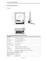
Page 14: ...zontal 60 vertical Pixel size 0 264 H x 0 264 W Viewing area 337 x 270 mm max pixel number 1280 x 1024 Colour 24 Bit colour depth 16 2 million Connections 3 USB ports Pull out USB 2 0 connection Power supply 12V DC min 60W separate power unit required Degree of protection iOP 19 TFT IP 50 Keyboard IP 68 Ambient temperature Storage temperature 5 C 35 C 25 C 55 C Weight approx 15 kg ...

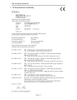
Page 15: ...r Elektrizität ESD EMC Testing and measurement techniques Electrostatic discharge immunity test EN 61000 4 4 2012 EMV Prüf und Messverfahren Prüfung der Störfestigkeit gegen schnelle transiente elektrische Störgrößen Burst EMC Testing and measurement techniques Electrical fast transient burst immunity test EN 61000 4 5 2007 EMV Prüf und Messverfahren Prüfung der Störfestigkeit gegen energiereiche ...

Reviews: