Description of the drive module
Positioning module IMD20, IMD40
VCC
VCC
12
0
12
0
2K
2
2K
2
2K
2
2K
2
2K
2
2K
2
12
0
Encoder B
Encoder Z
Encoder /A
Encoder /B
Encoder /Z
3
2
5
13
11
4
9
10
15
14
7
6
1
12
Y1
Y2
Y3
Y4
En1
B4
A4
B3
A3
B2
A2
B1
LTC489-SOL16
A1
En2
Encoder A
+5V Encoder
VCC
CAN
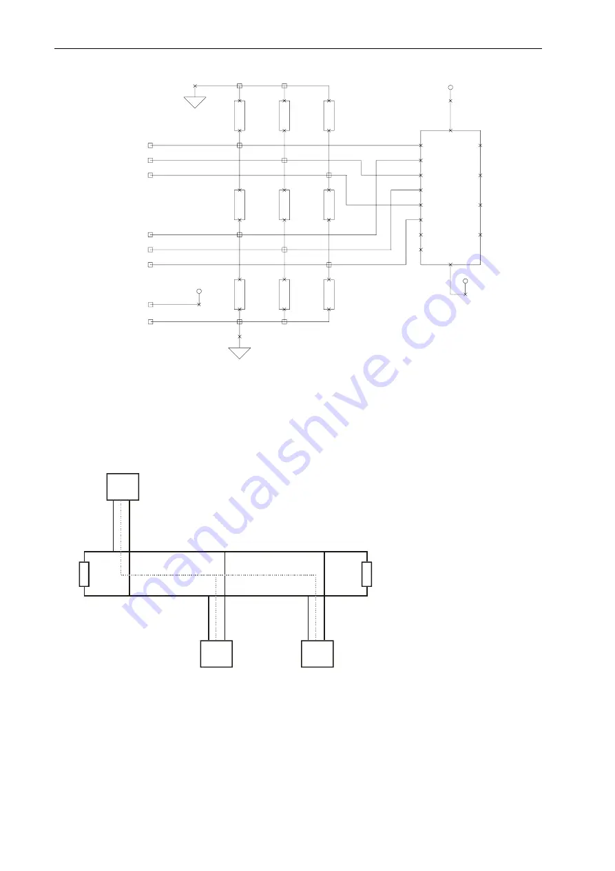
The structure of the C
is to be realised so as to guarantee that a 120 ohm terminating
resisto is provided o
s. On the drive module itself exists a terminating resistor. It is
activa
by the DIP sw
N terminator. The stub lines leading from the bus to the individual
modu
should not be l
n 50 cm in case of a baud rate of 1 Mbit/s.
Encoder GND
an network
r
n both side
ted
les
itch CA
onger tha
12
0
12
0
Axis 1
Axis n
…
Device
CAN High
CAN Low
CAN GND
For the CAN wiring, it is recommended to use twisted shielded cables with a characteristic
impedance of 108 to 132 ohms. In case of very small network extensions, it may be possible to
dispense with the connection of the reference potential (CAN ground) (not recommended).
26


