background image

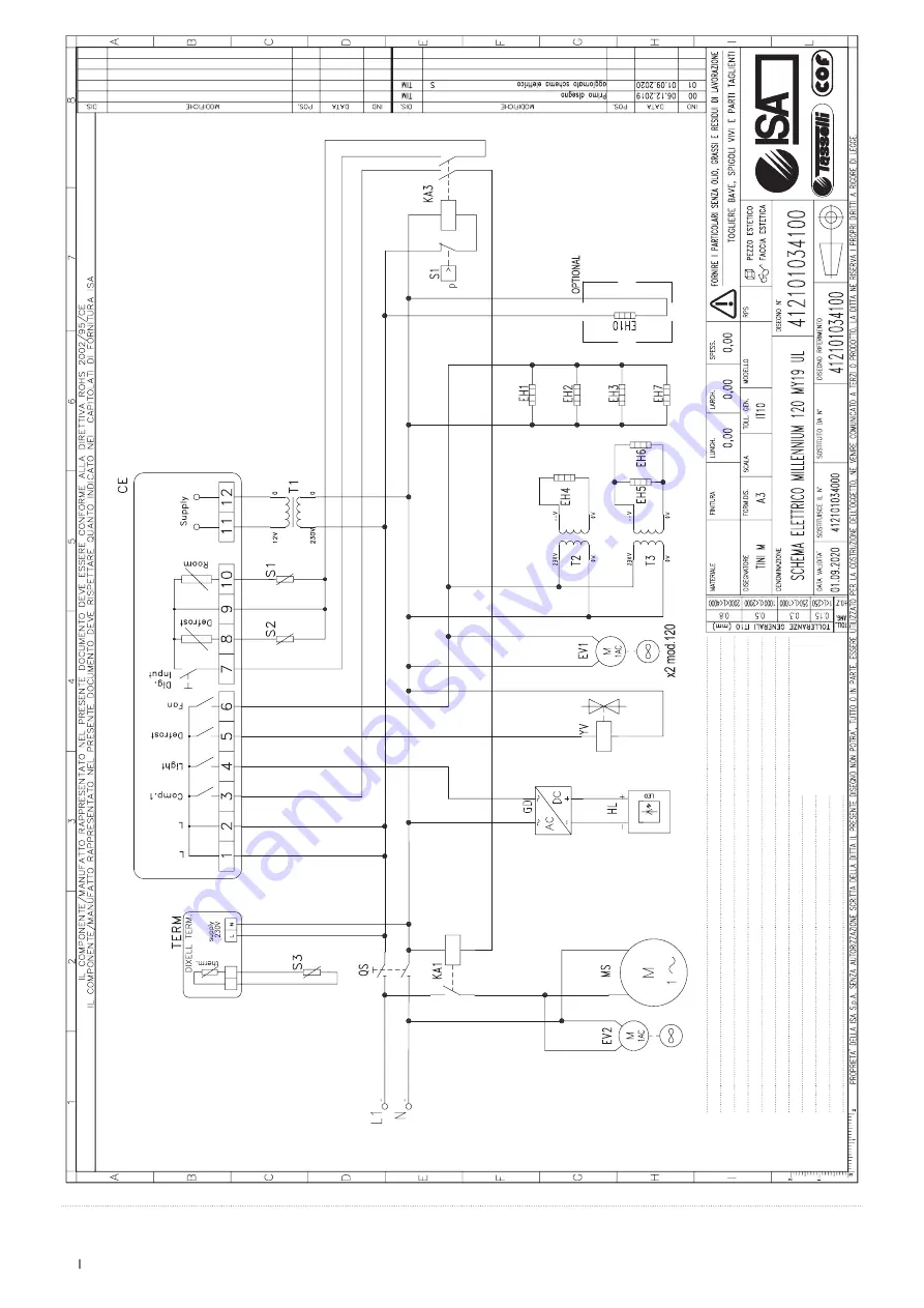
WIRING DIAGRAM

45

MILLENNIUM

EN 428001275137

Use and maintenance manual

S1

TEMPERA

TURE PROBE

EH10

DRIP DEFROSTING HEA

TING RESIST

OR

TERM

THERMOMETER

S2

DEFROST PROBE

EV1

EV

APORA

TOR F

AN

CE

ELECTRONIC C

ONTROL BO

ARD

S3

THERMOMETER PROBE

EV2

CONDENSER F

AN

KA1

COMPRESSOR RELA

Y

EH1

HEA

TINGRESIST

OR W

ORKING SURF

ACE

GD

LED PO

WER SUPPL

Y

KA3

PRESSURE SWIT

CH RELA

Y

EH2

SIDE HEA

TING RESIST

OR

HL

LED LAMP

S1

PRESSURE SWIT

CH

EH3

SIDE HEA

TING RESIST

OR 

MS

COMPRESSOR

QS

MAIN SWIT

CH

EH4

HEA

TED FRONT GLASS

T1

TRANSFORMER C

ONTROL

EH5

HEA

TED GLASS SIDE

T2

TRANSFORMER

EH6

HEA

TED GLASS SIDE

T3

TRANSFORMER

EH7

RESIST

ANCE OF FRONT

AL HEA

TING

YV

DEFROST SOLENOID V

AL

VE

Summary of Contents for Millennium LX Gelato

Page 1: ...nd maintenance manual ISA S p A Via Madonna di Campagna 123 06083 Bastia Umbra PG Italie T 39 075 801 71 F 39 075 800 09 00 E customerservice isaitaly com www isaitaly com Millennium Gelato Pastry LX Gelato ST Gelato LX Pastry ST Pastry ...

Page 2: ...PACKING 17 12 2 MANUAL HANDLING 19 12 2 1 REAR HANDLES OPERATOR SIDE 19 12 2 2 SIDE HANDLES OPTIONAL 20 12 3 ENVIRONMENTAL CONDITIONS 22 12 4 ELECTRICAL CONNECTION 22 12 5 POSITIONING LEVELLING 22 12 6 SIDE BY SIDE INSTALLATION 23 12 7 WALL MOUNTING 24 13 COMPOSITION 25 14 USE 26 14 1 LOAD LIMITS 26 14 2 DISPLAY LOADING LIMITS 27 14 3 GLASS FRONT OPENING 28 14 4 OPENING CLOSING OPERATOR SIDE 29 14...

Page 3: ... the manual Danger Live electrical parts Attention hazard Information Eye check Danger Slipping Danger Tripping Earthing Use of protective clothing Requests for maintenance or operations must be carried out by qualified staff or technical after sales centres Important information Operations that must be performed by two persons Notes warnings Waste disposal Recyclable materials ...

Page 4: ... no younger than 8 and by persons with reduced physical sensory or mental capabilities or lacking experience or necessary knowledge as long as supervised or after having received training regarding safe use of the equipment and have an understanding of the inherent risks involved Do not allow children to play with the device The cleaning and maintenance that the user will carry out must not be und...

Page 5: ...ucted by qualified personnel after the appliance has been prepared adequately HAZARD Unauthorised tampering or replacement of one or more parts of the appli ance use of accessories that modify the use of the same and use of spare parts different to those recommended can become the cause of injury HAZARD Any work conducted on the appliance must involve disconnection from the power socket and in any...

Page 6: ...ts correct use in particular the techni cal description of the various functional units accessories and safety systems opera tion use of instrumentation and interpretation of any diagnostic warnings main pro cedures and information relating to the ordinary maintenance operations For correct use of the appliance the working environment should comply with current health and safety standards The safe...

Page 7: ...personnel and damage to the equipment components and control unit The user can contact the dealer to request additional information not contained in this document or suggest improvements at any time Before delivery to the customer it is essential that the specialised technical staff check that the equipment is working correctly to ensure maximum per formance is obtained REFRIGERANT R744 The refrig...

Page 8: ...ing system present in the room ATTENTION Maintenance must be carried out by trained technical personnel authorised to work on flammable refrigerants REFRIGERANT R600a The refrigerant R600a is a gas that is compatible with the environment but is highly flammable Be very careful when transporting and installing the appliance and during scrapping to avoid damaging the refrigerant circuit pipes IN THE...

Page 9: ...eon LED lights etc if not due to manufacturing defects Calls for installation technical instructions adjustments condenser cleaning If the seller s technical staff detect any tampering unauthorised repairs or inappropriate use of appliance the warranty will be invalidated Shipment of components covered by the warranty is freight collect only Any damage to the appliance detected at the time of deli...

Page 10: ...ODEL NAME 5 ARTICLE 6 PRODUCTION DATE 7 PRODUCTION ORDER 8 CUSTOMER ORDER 9 PRODUCT CLASS 10 SERIAL NO 11 OWNER REGISTRATION NUMBER 12 POWER SUPPLY VOLTAGE 13 SUPPLY FREQUENCY 14 FUSE VALUE 15 LAMP POWER 16 ELECTRICAL RESISTOR ABSORPTION 17 NOMINAL POWER NORMAL OPERATION 18 POWER DEFROSTING 19 MINIMUM PRESSURE 20 MAXIMUM PRESSURE 21 SAFETY CLASS 22 RATED CURRENT 23 CURRENT DURING DEFROSTING 24 SHE...

Page 11: ...ppliance devices regularly 5 5 WARNING SIGNS IF ANY The equipment is equipped with danger attention and obligation warning plates defined in accordance with the legislation on graphic symbols to be used on the systems The plates are located where they are clearly visible ATTENTION Any warning plates on the appliance must not be removed The user is responsible for replacing warning signs that owing...

Page 12: ...ces It is strictly forbidden to make any type of electrical modification to avoid creating additional hazards and consequent unforeseen risks 6 2 FIRE DANGER In the event of a fire immediately disconnect the master switch from the main power supply line 6 3 EXPLOSIVE ATMOSPHERE 6 4 SLIPPING DANGER Any leaks in the areas surrounding the appliance may cause personnel to slip Check that there are no ...

Page 13: ...rious materials according to their similar features Check the type of refrigerant on the plate inside the counter remove the refrigerant and dispose of it through the authorised services Disconnect the evaporator condenser compressor pipes and fans the tubes being made of copper aluminium steel and plastic must be disposed of separately After removing all the casings and the various components fro...

Page 14: ...ical sockets Cleaning the condenser unit filter If present Cleaning the defrosting water collection tray TECHNICAL ASSISTANCE Cleaning the water collection tank Inside the tank if present Condenser cleaning Control of oil level of compressor Where present Drainage discharge of air tank Where present Control of pneumatic connections Where present Check the integrity of chiller system piping Inspect...

Page 15: ...ontrol unit If the electronic control board is used on appliances with R290 cool ant it must only be replaced with an original spare part supplied by the manufacturer Replace the temperature probes only after having ascertained which of them is inefficient Technical Assistance Condenser unit blocked by dust or dirt in general Clean the condensing unit thoroughly The condensing unit in particular o...

Page 16: ...uitable refrigerated container to ensure proper storage Open the equipment and wait for it to reach room temperature and then clean it Leave the door sliding panels open by 25 32 1 3 16 inch so as to guarantee circulation of the air and prevent the formation of mould and bad smells inside the appliance The appliance with or without its packaging should be carefully stored inside warehouses or in a...

Page 17: ...osed of in accordance with the local regulations Please destroy plastic bags to prevent them from becoming hazardous to children suffocation 12 1 UNPACKING ATTENTION Handling of the equipment must only be performed using a forklift truck of adequate power with respect to the weight of the equipment and operated by qualified personnel during this operation the equipment must strictly be positioned ...

Page 18: ...18 MILLENNIUM EN 428001275137 Use and maintenance manual 3 4 5 29 32 MAX 28 11 32 MAX ...

Page 19: ...75137 Use and maintenance manual 12 2 MANUAL HANDLING ATTENTION HANDLES To handle the equipment it is absolutely necessary to install the special handles provided as indicated below NO NO YES 12 2 1 REAR HANDLES OPERATOR SIDE ...

Page 20: ...20 MILLENNIUM EN 428001275137 Use and maintenance manual 12 2 2 SIDE HANDLES OPTIONAL 1 Ø 5 16 Ø 5 16 Ø 5 16 Ø 1 8 ...

Page 21: ...21 MILLENNIUM EN 428001275137 Use and maintenance manual 2 3 5 32 ...

Page 22: ...Check on the socket that the power supply voltage provides rated voltage 10 when you start up the compressor The plug should be directly connected to the electrical socket It is forbidden to connect the plug to the socket by means of multiple socket extensions or adaptors The plant power supply socket must be fitted with a disconnection device from the mains electricity dimensioned to the load and...

Page 23: ...23 MILLENNIUM EN 428001275137 Use and maintenance manual 12 6 SIDE BY SIDE INSTALLATION The equipment can be placed side by side in the different modules as indicated below ...

Page 24: ...nd maintenance manual 12 7 WALL MOUNTING ATTENTION It is fundamental to respect the distances indicated inch for correct installation of the appliance 19 11 16 19 11 16 39 3 8 19 11 16 19 11 16 19 11 16 39 3 8 19 11 16 19 11 16 19 11 16 ...

Page 25: ...board or remote condensing units Electrical system Electronic command panel Insulated monolithic structure in ecological polyurethane Internal LED lighting Standard Adjustable shelf LED lighting Optional Closure on operator side with self rolling curtain plexiglass sliding doors Front glass opened manually LX Front glass tilted manually ST Adjustable shelves 1 2 Pastry Standard Swivel casters with...

Page 26: ...ed above THE APPLIANCE IS INTENDED FOR PROFESSIONAL USE Non permitted uses Preservation of products Displaying and or preserving of non food products chemicals pharmaceuticals etc ATTENTION It is fundamental not to exceed the load limits indicated in order not to alter the correct air circulation and thus to prevent a high product temperature The limits indicated refer to a static and evenly distr...

Page 27: ...IUM EN 428001275137 Use and maintenance manual 14 2 DISPLAY LOADING LIMITS ATTENTION It isessential to respect the indicated loads 1 1 1 1 2 4 3 2 4 3 120 170 220 1 44 44 44 2 22 33 44 3 22 33 44 4 132 176 231 lb ...

Page 28: ...ILLENNIUM EN 428001275137 Use and maintenance manual 14 3 GLASS FRONT OPENING ATTENTION The glass front can be opened manually as shown below and has a limited opening never force beyond the permitted limit ...

Page 29: ...rect closing incomplete incorrect closure negatively impacts the performance of the equipment and on the excessive accumulation of ice on the inner walls PLEXIGLASS SLIDING DOORS VARIATION ATTENTION Open and close manually without forcing and ensure complete correct closing incomplete incorrect closure negatively impacts the performance of the equipment and on the excessive accumulation of ice on ...

Page 30: ...428001275137 Use and maintenance manual ADJUSTABLE SHELVES 14 5 The equipment can be equipped with one 1 or two 2 shelves adjustable in depth as indicated below Pastry 1 2 Each shelf is adjustable in depth 1 31 32 inch ...

Page 31: ...l dimensions Length L inch 45 29 32 65 13 32 84 7 8 Depth P ST inch 41 1 2 LX inch 42 9 16 Height H inch 53 7 16 Weight net lb 441 573 2 793 6 15 1 Gelato CONFIGURATIONS ST LX 5 Lt Standard 14 3 16 x 6 1 2 x 4 23 32H 5 Lt Large 14 3 16 x 9 27 32 x 3 2 32H Ice Cream container Optional 120 12 8 170 18 12 220 24 16 ...

Page 32: ...137 Use and maintenance manual 15 2 TECHNICAL PLANS SUPPORT FEET 1 1 4 inch DISCHARGE Ø 31 32 inch GAS CONNECTION CABLE OUTPUT CONTROL PANEL WHEEL WHEEL WITH BRAKE CUSTOMER SIDE PASSAGE OF PIPES THROUGH THE PLATFORM 120 170 220 ...

Page 33: ...20 170 220 Tray Shelf 41 7 32 x 31 1 2 inch ST LX 120 170 220 External dimensions Length L inch 45 29 32 65 13 32 84 7 8 Depth P ST inch 41 1 2 LX inch 42 9 16 Height H inch 53 7 16 Weight net lb 441 507 573 2 40 23 32 x 9 7 16 inch 60 3 16 x 9 7 16 inch 79 11 16 x 9 7 16 inch 60 23 32 x 31 1 2 inch 80 5 32 x 31 1 2 inch ...

Page 34: ...137 Use and maintenance manual 16 2 TECHNICAL PLANS SUPPORT FEET 1 1 4 inch DISCHARGE Ø 31 32 inch GAS CONNECTION CABLE OUTPUT CONTROL PANEL WHEEL WHEEL WITH BRAKE CUSTOMER SIDE PASSAGE OF PIPES THROUGH THE PLATFORM 120 170 220 ...

Page 35: ...e plug is fitted with an earth contact and that there are no multiple sockets connected to it THE EQUIPMENT STARTS AUTOMATICALLY NO 17 CONTROL PANEL SWITCH OFF OFF Remove the power plug from the socket supplied by the customer ATTENTION The electronic control unit is installed already programmed any changes to the control unit settings can be performed by qualified technicians only ...

Page 36: ...ramming it scrolls through the parameter codes or increases their value When pressed for 5 seconds it enables disables ventilation depending on the setting DISPLAY MAXIMUM TEMPERATURE Press and release the key the message Hi will be displayed followed by the maximum temperature reached Press the key or wait 5 seconds to display the normal temperature again DUAL TEMPERATURE FUNCTION Pt Positive Tem...

Page 37: ...ss Energy saving in progress Continuous cycle in progress Auxiliary relay active Fans stopped by key KEYS SET POINT DISPLAY Press and release the key the set point will be displayed immediately to go back to the temperature wait 5 seconds or press the key again CHANGE Press the key for at least 2 seconds the set point will be displayed and the C LED will start to flash To change the value use the ...

Page 38: ...use P1 Faulty temperature probe P2 Faulty first evaporator probe P3 Faulty second evaporator probe HA High temperature alarm LA Low temperature alarm EA External alarm CA External alarm i1F bAL Pressure switch alarm i1F PAL oFF Instrument in stand by dA Door open POF Unlock door POn Keyboard locked ...

Page 39: ...move the product contained in the refrigerated compartment and place it immediately in a suitable refrigerated container to ensure proper storage 2 Turn off the equipment 3 Remove the manually removable accessories e g slides grids ice cream trays etc 4 Wait at least 4 or 6 hours for any ice on the evaporator to melt completely before proceeding with cleaning of the appliance We suggest in this re...

Page 40: ...every piece of equipment on the condensing unit has reached a temperate close to room temperature Perform the following steps to access the condensing unit 18 2 CONDENSER UNIT REMOVABLE 1 Remove the filter as indicated FILTER Remove the rear grids as indicated 2 Remove the fixing brackets as indicated 3 ...

Page 41: ...densing unit using a dedicated soft bristle brush and a vacuum cleaner carry out the operation taking care not to bend the condensing unit springs 18 3 FILTER Manually extract the filter as indicated Vacuum dust from the filter Wash with running water and wait for it dry completely before reassembling it A B ...

Page 42: ...ESENT Clean based on use and as needed and in certain environmental conditions e g high humidity low environmental temperature presence of dust etc in order to avoid the incorrect and complete evaporation of the water and or the presence of unpleasant odours Sanitise the tray with specific products ...

Page 43: ...ENSER FAN CE ELECTRONIC CONTROL BOARD EH1 HEATINGRESISTOR WORKING SURFACE GD LED POWER SUPPLY R9 DELAY RELAY EH2 SIDE HEATING RESISTOR HL LED LAMP KA1 COMPRESSOR RELAY EH3 SIDE HEATING RESISTOR MS1 COMPRESSOR 1 KA3 PRESSURE SWITCH RELAY EH4 HEATED FRONT GLASS MS2 COMPRESSOR 2 S1 PRESSURE SWITCH EH5 HEATED GLASS SIDE T1 TRANSFORMER CONTROL QS MAIN SWITCH EH6 HEATED GLASS SIDE T2 TRANSFORMER EH7 RES...

Page 44: ...H1 HEATINGRESISTOR WORKING SURFACE EH10 DRIP DEFROSTING HEATING RESISTOR EV1 EVAPORATOR FAN EV2 CONDENSER FAN EV3 FRONT FAN GD LED POWER SUPPLY HL LED LAMP MS COMPRESSOR T1 TRANSFORMER CONTROL T2 TRANSFORMER TERM THERMOMETER CE ELECTRONIC CONTROL BOARD KA1 COMPRESSOR RELAY KA3 PRESSURE SWITCH RELAY S1 PRESSURE SWITCH QS MAIN SWITCH ...

Page 45: ...ETER PROBE EV2 CONDENSER FAN KA1 COMPRESSOR RELAY EH1 HEATINGRESISTOR WORKING SURFACE GD LED POWER SUPPLY KA3 PRESSURE SWITCH RELAY EH2 SIDE HEATING RESISTOR HL LED LAMP S1 PRESSURE SWITCH EH3 SIDE HEATING RESISTOR MS COMPRESSOR QS MAIN SWITCH EH4 HEATED FRONT GLASS T1 TRANSFORMER CONTROL EH5 HEATED GLASS SIDE T2 TRANSFORMER EH6 HEATED GLASS SIDE T3 TRANSFORMER EH7 RESISTANCE OF FRONTAL HEATING YV...

Page 46: ...ER FAN CE ELECTRONIC CONTROL BOARD EH1 HEATINGRESISTOR WORKING SURFACE GD LED POWER SUPPLY R9 DELAY RELAY EH2 SIDE HEATING RESISTOR HL LED LAMP KA1 COMPRESSOR RELAY EH3 SIDE HEATING RESISTOR MS1 COMPRESSOR 1 KA3 PRESSURE SWITCH RELAY EH4 HEATED FRONT GLASS MS2 COMPRESSOR 2 S1 PRESSURE SWITCH EH5 HEATED GLASS SIDE T1 CONTROL UNIT TRANSFORMER QS MAIN SWITCH EH6 HEATED GLASS SIDE T2 TRANSFORMER EH7 R...

Page 47: ......

Page 48: ...MILLENNIUM EN 428001275137 Use and maintenance manual ...

Reviews:

Related manuals for Millennium LX Gelato