background image

QUICK START

4. Discovery

Discovery is a process that sets up network topology to be able to deliver data or commands to Nodes out of the
Coordinator direct range. Thanks to HWP just a couple of clicks and all is done. Discovered topology can directly be
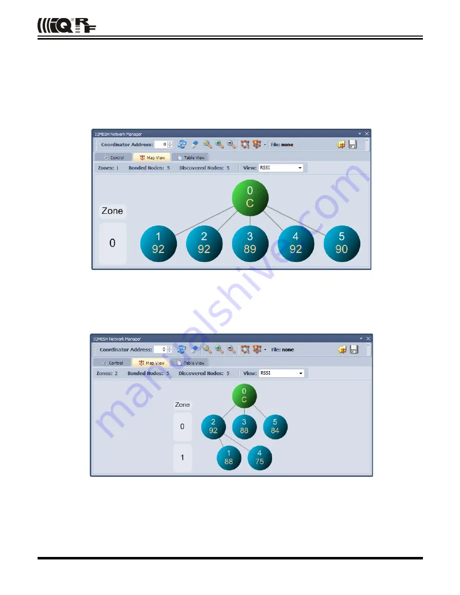
reviewed in window 

IQMESH Network Manager

, the 

Map View

  tab. Follow next steps to run Discovery and create

different types of topologies.

A.  Place all Nodes close to the Coordinator and click the 

Discovery

 button (in window 

IQMESH Network Manager

, the

tab 

Control

 → 

IQMESH

). If all Nodes are in direct range to the Coordinator the Discovery should take a few seconds

only. Switch to the 

Map View

 tab after finishing Discovery. The topology like in the screenshot below should appear.

B.  Place  Nodes  in   longer   distance   between   each   other   (with   respect   to   current  

RX   Filter

  selected   in  

TR

Configuration

). For test purpose it is recommended to reduce the range using a shielding, e.g. by inserting the kits

with DCTR modules into plastic bags with anti-static proofing.

D. Click the 

Discovery

 button. If not all Nodes are in direct range now, the Discovery process will take a bit longer.

The result can look like on the screenshot below:

Note

Displayed “topology” is only a tree visualization of parent Nodes (illustrating just the path which has been used to
discover individual Nodes) but not the routing structure. This does not mean that packets can be delivered through
displayed links only. Packets are delivered based on Directed flooding routing algorithm described in IQRF OS User
's guide.

© 2015  MICRORISC s.r.o.

www.iqrf.org

Quick_Start_Guide_IQRF_ 150805

Page 14

Summary of Contents for DS-DPA-02

Page 1: ...IQRF Quick Start Guide For IQRF OS v3 07D and higher For IQRF IDE v4 30 and higher 2015 MICRORISC s r o www iqrf org Quick_Start_Guide_IQRF_ 150805 Page 1...

Page 2: ...and uploading procedure 8 Other development test and service utilities 8 C programming 9 Design steps 9 Debug 10 Application examples 10 Quick start with HWP without programming 11 Demo HWP vs Genera...

Page 3: ...DS START 04 see below or DS DPA 02 see chapter DS DPA 02 development set contains all HW needed for effective start up DCTR transceivers RF transceiver modules DCTR 72DA fitting to SIM connector They...

Page 4: ...r charging but not for USB connectivity USB device DCTRs can also be hosted by CK USB 04A connected to PC via USB It enables to control the DCTR application from PC first of all by the IQRF IDE powerf...

Page 5: ...ug and play thanks to the E09 LINK program which is uploaded in all TR modules in development sets delivered from the factory It is one of Basic examples from the Startup package and can be uploaded w...

Page 6: ...r IQRF OS The functionality is given by the application program in C language This approach can be implemented also with TR transceivers without the DC prefix supporting only Demo hardware profiles Fo...

Page 7: ...ASCII text e g Windows Notepad can be used Notepad a great source code editor free by GPL License is very recommended Download it from www notepad plus plus org The editor is not necessary when using...

Page 8: ...essary when using hardware profiles without a Custom DPA handler Upload uploading the code into the DCTR module either a hardware profile possibly with a Custom handler or a user specific application...

Page 9: ...y add required IQRF or HEX file to the Project Project Add Existing Item and go to step 7 4 Add required source file one of examples e g CustomDpaHandler Timer E09 LINK c or empty template CustomDpaHa...

Page 10: ...the W register MCU accumulator should be used to distinguish the active breakpoint location Macro breakpoint w can be used for simplicity See IQRF macros h header file and basic example E06 RAM for ex...

Page 11: ...s are indicated by LEDs flashing by default DS DPA 02 development set To learn DPA usage development set DS DPA 02 can be used DCTR 72DAT IQRF smart transceiver 6 pcs CK USB 04A IQRF programmer and de...

Page 12: ...testing within the room select 15 For operating in real conditions select 0 for TR 7xD or 5 for TR 5xD This settings must be the same in the entire network Do not change other parameters for now Save...

Page 13: ...hould be cleared from the Coordinator memory first Click the Clear All Bonds in IQMESH Network Manager window tab Control IQMESH Number of bonded Nodes should be 0 see the screenshot below C Activate...

Page 14: ...eenshot below should appear B Place Nodes in longer distance between each other with respect to current RX Filter selected in TR Configuration For test purpose it is recommended to reduce the range us...

Page 15: ...dress in NADR box for Broadcast use address 0xFF and click the Send button Go to LED macros and click on macro Set LEDR on To switch all LEDs on fill in 0xFF in NADR and Click Send button Use various...

Page 16: ...SW1 close to USB connector Shortly press button SW2 Green LED shines for about 2 s Release the SW1 button immediately once the green LED stops shining If the node is successfully unbonded red LED is f...

Page 17: ...mplementation in IQRF TR modules It is needed only if you design one s own SPI master to communicate with the TR module TR module datasheet User s guides of development kits used IQRF USB drivers Inst...

Page 18: ...All information contained in this publication is intended through suggestion only and may be superseded by updates without prior notice No representation or warranty is given and no liability is assum...

Reviews: