8
i Po r t I W- 2 0 / I W- 2 1 / I W- 2 2
I n s t r u c t i o n M a n u a l
IMPORTANT: Do
not install the iPort wall plate in the same elec-
trical box as AC house wiring, a light switch, or any other high-
voltage device or control. The wall plate can share gang boxes
with other iPort wall plates or with controls such as A/B speaker
switches, infrared receivers, and volume controls, if these other
devices are rated as Class 2 devices according to the National
Electrical Code.
5. Use a stereo RCA audio cable to connect the wall plate’s A
UDIO
connectors to a source input on the local-zone audio system, as
shown in
Figure 4, page 7.
6. Insert the iPort utility box into the opening in the wall.
• First insert the top edge into the opening, then rotate the bottom
edge into the opening.
Note: The Roto-Lock system can accommodate a maximum
wall material thickness of 1
3
/
8
”.
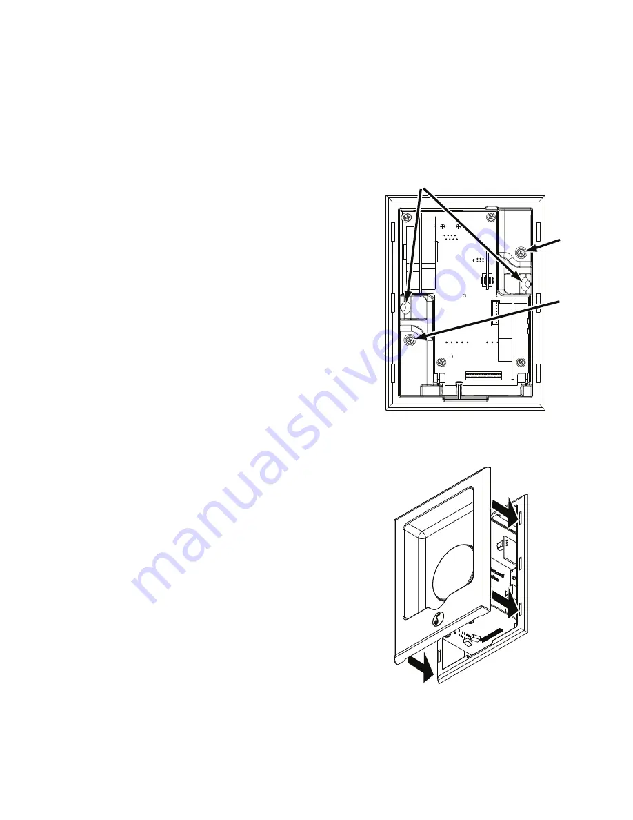
7. Hand-tighten the two Roto-Lock screws on the iPort utility box
as shown in
Figure 5. The Roto-Lock clamps will automatically rotate
into position behind the wall and begin clamping the iPort.
• When you notice resistance on the two screws, the iPort has been
clamped successfully.
IMPORTANT: NEVER over-tighten the Roto-Lock screws.
8. If there is a wall stud up against one side of the utility box that
prevents one Roto-Lock clamp from operating, secure the box by
hand-driving a 1½” #6 drywall screw (not provided) through the
angled hole on that side of the chassis and into the wall stud.
See
Figure 5.
IMPORTANT: Do not over-tighten the drywall screw.
9. Attach the iPort face to the utility box as shown in
Figure 6. Slide the
face all the way into the box until it fits snugly into place.
10. Plug the included DC power supply into the
Power connector on
the wall plate and into a wall outlet, as shown in
Figure 4, page 7.
Roto-Lock
Screw
Roto-Lock
Screw
If mounted next to
a stud, drive a 1½”
#6 drywall screw
here
Figure 5: Attaching the Utility Box to a Wall
Figure 6: Attaching the Face
to the Utility Box


