background image


PLDC01938 


                                                        REVISION    00 

                                                                                                                                         01/06/2011 
                                                                                                                                   TECHNICAL DEPT 
 

                                                                                                                                      Stavale 


- date 05/09/2011


140/195


11 

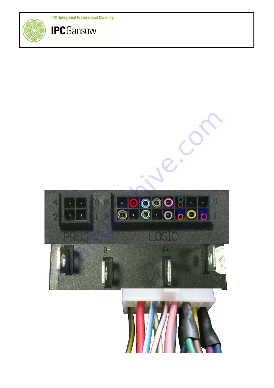
Place the front wheel in the straight position (to activate the steering sensor), sensor LED on, and proceed to 
measure the input voltage on the board between the BROWN wire, pin 11, (connected together with the 
green wire, corresponding to the Curtis interface board,  it indicates the reduction in speed to the control 
panel board) and the negative power contact B-. If everything is OK, the voltage will be +36 V. 

11a

   If there is no voltage, check the continuity of the wires and/or correct functioning of the steering sensor. If  


necessary adjust or replace it (see paragraph C5).  

12 

Read the output voltage between the YELLOW-BLACK wire, pin 8, and the positive power contact B+
There must be a voltage of -36 V. This voltage powers the drive contactor and is available only if point 13 is 
respected.  

13 

Bridge the “operator present” sensor (under the seat), make sure the parking brake is off, press the 
accelerator pedal lightly until you hear the “click” of the micro switch and proceed to read the input voltage 
between the WHITE-GREEN wire, pin 6, (INHIBIT) and the positive power contact B+. There must be a 
voltage of -36 V.  


Through the WHITE-GREEN wire, the control panel board supplies the drive board with a 
voltage of -36 V only if the conditions of operator present, parking brake off and accelerator 
pedal pressed are respected.  


If the control panel board malfunctions, the drive board does not function, as there is 
no INHIBIT input signal as described in point 13.   


16 


 8


1


LOGIC 


B+ 

PHOTO 296 

A2 

M- 

B- 

B+ 

Summary of Contents for CT 230 BT 105

Page 1: ...011 TECHNICAL DEPT CT 230 TECHNICAL SERVICE MANUAL Stavale DATE PLDC01938 REVISION DATE 01 06 2011 IPC GANSOW via Cartesio 39 42040 Villa Bagno RE Tel 0039 0522 266000 Fax 0039 0522 342045 info ipcleaning com ...

Page 2: ... accessibility Motor protection filter Type of float Squeegee Shape Width 1010 mm 1280 mm Mainbody material Blade material Pressure adjustment Raising system Blade replacement open the recovery tank fixed on the recovery tank upper Polyurethan 200 rpm High Density Polythene Ø 50 mm hose gear box standard type nylon 0 5 mm polyester net Electronic float with stop vacuum motor 956 W 2 stage electro ...

Page 3: ...7 5 Kg With battery empty tanks 750 Kg 320 Ah 777 5 Kg 320 Ah From operator ear Brush Pad From operator ear Microfiber Hand Body Safety systems Certification European 1100 W 1 yes traction motor wheel 1466 mm 300 mm accelerator pedal 6 5 km h 2 emergency switch fixed on the chassis 300 mm non markingrubber electro deposition coating and galvanised parts 440 mm 530 mm CE auto power off system opera...

Page 4: ...amme according to the surface and dirt to be removed P1 light cleaning programme P2 medium cleaning programme P3 heavy cleaning programme After the cleaning programme has been selected the machine chooses the advance speed and quantity of detergent then turns the suction and brush motors on 7 The machine can be operated without using the 3 cleaning programmes provided by the manufacturer In this c...

Page 5: ...ith the screws BRUSH ATTACHMENT RELEASE Attaching Press the Click Off On button The machine first performs a release operation then immediately afterwards enables the attachment operation Press the Click Off On button again to automatically attach the brushes Releasing Press the Click Off On button the machine releases the brushes TROUBLESHOOTING CHECK THE EMERGENCY BUTTON IS NOT PRESSED THE MACHI...

Page 6: ...60 PARAMETER MODIFICATION OUT OF THE DEFAULT VALUE COULD CAUSE AN INCORRECT WORKING OF THE MACHINE CONTACT IPC TECHNICAL DPT BEFORE ANY MODIFICATION To enter in the technical programming keep pushed the button P1 and P3 ref 4 and turn to1 the key ref 1 Display shows the first parameter UP 1 0 To pass from a paramater to another one use the ref 2 button To modify the default value use the the water...

Page 7: ...Pressure 060 Program 3 Pressure 040 Program 3 Brushes ON Program 3 Brushes ON Program 3 Suction ON Program 3 Suction ON Program 3 AUTO Program 3 Water 3 Program 3 AutoPowerOFF ON Program 3 AutoPowerOFF ON PARAMETER MODIFICATION OUT OF THE DEFAULT VALUE COULD CAUSE AN INCORRECT WORKING OF THE MACHINE CONTACT IPC TECHNICAL DPT BEFORE ANY MODIFICATION To enter in the user programming turn to 1 the ke...

Page 8: ...ers B1 A4 Replacing the head flaps Cleaning and replacing the solenoid valve Checking and or replacing the compensator Checking the draw of the suction motor Replacing the suction motor A2 A1 Checking the current draw of the brush motors Checking and replacing the brush motor carbon brushes Checking head actuator current draw Checking actuator operation manually Replacing the head actuator Checkin...

Page 9: ...erator IMPORTANT Indicates the need for attention in order to avoid a series of consequences which the Manufacturer reserves the right to make modifications without warning Although your machine may differ appreciably from the illustrations in this document safety and the information contained in this manual are guaranteed PLDC01938 REVISION 00 01 06 2011 TECHNICAL DEPT Stavale could cause damage ...

Page 10: ...rs Checking operation of the detergent pump solenoid valve Checking squeegee actuator operation manually Replacing the squeegee actuator Checking head actuator operation manually on the bench Replacing the squeegee flaps Checking the draw of the suction motor Replacing the suction motor SQUEEGEE AND ACTUATOR ASSEMBLY Checking electromechanical actuator draw TANKS SUCTION ASSEMBLY Checking and or r...

Page 11: ...OOTING Contactor TL1 functions and TL2 drive Disassembling and or replacing the chem dose pump WIRING DIAGRAM Connecting the chem dose switch on the control panel optional FUNCTIONS CIRCUIT BOARD Removing the functions circuit board IMPORTANT ELECTRICAL COMPONENTS CONTROL PANEL BOARD ELECTRICAL CIRCUIT SLOW STEERING SENSOR Replacing and or regulating the steering sensor CONTROL PANEL BOARD DRIVE A...

Page 12: ...urning the ignition key to position 0 Disconnect the electronic circuit from the batteries by means of the Anderson connector with handle i INFORMATION Particularly important instructions In this Technical Service Manual the terms RIGHT and LEFT are used to indicate the sides of the machine They always refer to the direction of travel In this Technical Service Manual you may find the version of ma...

Page 13: ... strip of 850 mm and the BT 105 with a cleaning strip of 1050 mm Apart from the size the two heads also differ in the type of motor used The BT 85 version mounts a 400 W motor the same motor as on the CT 160 with free cooling while the BT 105 version mounts a 500 W motor with forced cooling by means of a fan in the top part of the motor itself protected by a casing which also serves as an air conv...

Page 14: ...t the same time turn the key B to position 1 Keep the buttons pressed until UP 1 0 is displayed 5 Press the display button C to scroll through the menu until you reach UP B 0 Press the water regulation and buttons D to select 1 only two values appear 0 and 1 This setting enables the current draw of both motors together during the washing phase to be displayed For disk brush versions only BT 85 BT ...

Page 15: ...am 1 AutoPowerOFF ON 12 Press the and buttons D to change the setting from ON to OFF 13 Keep the display button C pressed for a few seconds to save the new settings For practical reasons AutoPowerOff is disabled to allow the brushes to be used independently from the drive With AutoPowerOff enabled ON the brushes are connected to the accelerator pedal and each time the accelerator pedal is released...

Page 16: ...the button F to release the brushes from the drive disks the LED G will flash At the end of the operation remove the brushes 16 Press the button F to perform a brush attachment operation without attaching the brushes LED H will flash 17 After the attachment phase without attaching the brushes LED off press the display button C to scroll through the menu The display changes from the volts to an ind...

Page 17: ...e calculated considering the set tolerance T0 X in this case in Program 1 During normal use the control unit dedicates a maximum of 50 A to the brush motor and limits output if the current draw exceeds 65 A for more than 10 ten seconds The control unit controls the head raising and lowering actuator in order to maintain the set pressure In output limitation situations the control unit commands rai...

Page 18: ...o a relatively smooth area of floor in order to obtain a constant reading 26 To avoid wasting water press the and buttons D to set the quantity of water to minimum one LED on only 3 0 5 0 litres minute This is sufficient to wet the floor and avoid overheating the brush bristles 27 Press the manual brush button E to operate the brushes 28 Read both draw values lsp brush motor draw during the washin...

Page 19: ...rd to complete the check about 3 seconds 9 Press the button C to set the quantity of water delivered during the washing phase to zero 10 Press the button B nearest the left side of the display for at least 10 seconds 11 The first parameter the language is displayed 12 Press the same button B on the left of the display to scroll through the parameters 13 Reach Program 1 AutoPowerOff 14 Press the wa...

Page 20: ...ut disconnecting them connect the clamp meter to first one then after performing the test the other to read the current draw of both brush motors separately 23 The polarities of the left brush motor connector F1 are the opposite to those of the right brush motor connector so that the motor rotates in the opposite direction clockwise 24 When correctly connected the electrical connection of the brus...

Page 21: ...note the value for the first motor after a few seconds rotation When button G is pressed the brushes will operate with the Program 1 settings 27 Press the brush button G again to stop the test in order to connect the clamp to the second motor 28 Connect the clamp meter to the red wire of the connector F2 on the right motor F 29 Press the brush button G again to lower the head and start the motors ...

Page 22: ...s approximately equal to the value read on the control panel display check the draw during the washing phase as described below CHECKING THE CURRENT DRAW OF THE BRUSH MOTORS DURING WASHING 31 Proceed to read the draw of the two motors separately with the STANDARD brushes mounted both brushes must be mounted As well as verifying the draw of the motors separately the test also verifies that the brus...

Page 23: ...ary or rotating following impact between the brushes and fixed components attachment of damaged brushes or an unsuccessful attachment operation 34c If the values do not respect the indications given in point 34 and are higher the head and brushes are in good condition and there is no friction or interference Proceed to check the carbon brushes on the brush motor drawing the most current A or both ...

Page 24: ...ed below Disassembly 1 Move the machine to the tank draining area and empty the detergent and dirty water tanks 2 Move the machine to a flat dry surface The operation can be simplified by using an autolift if available 3 Press the pedal A to put the parking brake on 4 Press the button B to release the brushes 5 Turn the ignition key to position 0 6 Remove the brushes from under the head 7 Unscrew ...

Page 25: ...to perform a brush release action without the brushes attached 12 Wait for the LED indicating that the brushes can be attached to flash then press the button B again to perform an automatic brush attachment operation without attaching the brushes 13 With the head fully lowered press the emergency button E to block the position and avoid the head returning to the standby position 14 Disconnect the ...

Page 26: ...or or motors by means of the Anderson connectors G and remove the terminals G1 from the connectors G 16 Remove the sheath H from the motor power wires 17 Gently lift up the air conveyor D1 running the motor power wires D3 through the cable glands D4 on the air conveyor D1 G G G1 PHOTO 35 G H D1 D1 D D D3 D3 D4 PHOTO 36 ...

Page 27: ...ith a felt pen to facilitate positioning during remounting 20 Pull the plastic spring clip D7 outwards to remove the metal band D5 and check the carbon brushes D7 21 Identify the spring D8 pressing the carbon brush D7 on the rotor D9 For convenience operate on the outermost carbon brush 22 With a wire hook lift the spring D8 23 Remove the carbon brush D7 from its housing and measure the length D5 ...

Page 28: ... replace All four carbon brushes must be replaced at the same time and if the operating hours of the two brush motors mounted on the head are the same all eight carbon brushes must be replaced together 26 With a 7 mm spanner unscrew the nut D9 fixing the eye terminal of the carbon brush to the mount 27 Pay attention to the washer D10 under the nut D9 If it falls inside the motor you may have to di...

Page 29: ... Check that all the connecting wires D11 are tightly fastened to their contacts and the nuts are tight Reassembly 1 To mount the new carbon brushes perform the disassembly operations in reverse 2 Before mounting the new carbon brushes pay particular attention to the dimensions The brushes must slide freely and be the same size apart from the length 3 Always insert the washer D10 between the eye te...

Page 30: ...motor D until you reach the carbon brushes I 2 Identify the crosshead screw I1 and unscrew it to disconnect the carbon brush I2 3 With a hook as for the previous motor lift spring I3 and extract the carbon brush I2 Checks 4 As well as checking the dimensions of the carbon brush I2 also check the state of wear of the rotor I4 where it slides against the carbon brushes and the contact surface of the...

Page 31: ... 11 mm otherwise it must be replaced 7 When replacing compare the new carbon brush with the one being replaced and or the measurements below Only the length may differ 8 Make sure the carbon brushes slide freely in their housing Reassembly 1 Before mounting the new carbon brushes clean inside the motor by blowing with a jet of compressed air concentrating on the area around the carbon brushes and ...

Page 32: ...ered by means of an electromechanical actuator Controlled from the control panel board as well as positioning the head washing or standby the actuator also regulates the head to the pressure set by the operator on the control board When replacing it is very important that the characteristics given on the old actuator board are respected PHOTO 46 i ...

Page 33: ...if the voltage drops to 31 V while the power draw remains at 360 W the current draw of the motor A must increase to 11 6 A Head actuator current draw can be tested in two ways The person responsible for the measurement can decide whether to measure the current draw on the fuse wires quicker but the tanks must be emptied or using the wires connected to the control panel board longer as the control ...

Page 34: ...s to the fuse holder 9 Place the ignition key in position 1 10 Press the button B to set water flow to zero no LED on 11 The fuse holder C is located alongside the Anderson plug D for recharging the batteries 12 Identify the 5A head actuator fuse E with two blue wires 13 Insert the jaws of the clamp meter between the two blue wires connected to the 5A actuator fuse E A B PHOTO 48 PHOTO 49 E D C PH...

Page 35: ...ments do not correspond to those specified but are higher 19a Check that the head parallelogram is free to move up and down without interference and that there are no squeaks or rubbing sounds 19b Check the draw of the actuator without load detached from the head or replace the actuator with a new one The circuit board controls the head actuator during raising and lowering powering it through the ...

Page 36: ...elow 3 Move the machine onto a flat dry area of floor 4 Disconnect the operator present sensor connector A and bridge it with a suitable connector 5 Press the button B to set water flow to zero no LED on 6 Turn the machine off and press the pedal to put the parking brake on 7 Remove the control panel by unscrewing the six screws C fixing it to the front panel 8 Lift the control panel and identify ...

Page 37: ...he brushes mounted preferably new 11 Press the button E to lower the head 12 Read the draw in amps and compare with the table below 13 Press the button E to raise the brushes 14 Read the draw in amps and compare with the table below 15 If the values are within the range shown in the table below everything is within the norm Disconnect the clamp meter and remount the control panel E PHOTO 59 D5 D6 ...

Page 38: ... are no squeaks or rubbing sounds 16b Check the draw of the actuator without load or replace the actuator with a new one The circuit board controls the head actuator during raising and lowering powering it through the MOS FET with an ON OFF command switch type If current draw is high or there is a short circuit the 5A fuse trips and current to the actuator is shut off Draw A amps Min Max During lo...

Page 39: ...mpletely empty both tanks 3 Move the machine onto a flat dry area of floor 4 Turn the machine off and put the parking brake on 5 Disconnect the batteries from the machine electronics via the Anderson connector C 6 Raise the detergent and dirty water tanks 7 Identify the two head actuator connectors B and D 8 To carry out the tests you need only disconnect the connector B the larger 5 way connector...

Page 40: ...e burns out at the beginning of the test the actuator motor might be in short circuit Disassemble the actuator as explained in the following paragraph 15 If the fuse is not blown but the actuator does not move there might be a problem with the micro switches in the actuator Disassemble the actuator as explained in the following paragraph and check the internal micro switches as explained in paragr...

Page 41: ... sought elsewhere wiring control panel board 23 Check the actuator absorption value in any case by measuring the signal from the wires A1 or A2 used for the connection or from the fuse box as described in paragraph A2 1 24 If on the other hand the actuator does not move remove it take it to the bench and test the internal micro switches see paragraph A2 4 25 If it starts to move then stops because...

Page 42: ... by pressing pedal A 4 Turn the ignition key to position 0 5 Unscrew the knob B by turning it anticlockwise to release the tanks Raise the tanks 6 Switch the machine on by turning the key to position 1 7 Press the button C to release the brushes 8 Remove the brushes from under the head 9 Wait for the LED D to start flashing indicating that the brushes can be attached Press button C again to perfor...

Page 43: ...es by means of the connector F turn the ignition key to position 0 restore the emergency button E to the original position 12 Disconnect power to the electromechanical actuator G by means of the watertight connectors G1 and G2 on the main machine wiring located on the left of the machine under the battery container 13 Cut and remove the plastic tie H fastening the actuator wire G to the machine ch...

Page 44: ... 05 09 2011 33 195 14 Use a pair of circlip pliers to remove the circlip I 15 With a wide screwdriver or lever push the actuator arm L downwards and at the same time use a screwdriver to push the pin M completely out of its housing M M L PHOTO 73 G I I PHOTO 72 ...

Page 45: ...convenience given the tight space available use a no 17 ratchet spanner 18 If the solenoid valve wires and pump wire make it difficult to remove the actuator disconnect them Reassembly 1 Before replacing the electromechanical actuator G test it on the bench as described in the following paragraph 2 To mount the new actuator perform the disassembly operations in reverse G M PHOTO 74 PHOTO 75 G ...

Page 46: ...el to the circuit board controlling raising and lowering In addition in the case of the actuator in question head pressure and raising reaching the top micro switch not only notifies the control panel board that the end of travel has been reached but also through the control panel display warns when the brushes are worn and need changing The linear travel of the cam K on the rod actuates one of th...

Page 47: ...ceed with the electrical test as described below 4 Obtain two wires E1 E2 with different colours see photograph below with plugs for insertion in the terminals of the connector B 5 Also obtain a bridge D for the fuse connector C and connect it 6 Place the actuator A with the axis of the hole in the rod A1 on the same plane as the hole in the rigid support A2 For testing the actuators can be powere...

Page 48: ...f the actuator Let the micro switch in the body stop the rod A1 emerging 11 Travel of the rod A1 is 100 mm so measuring it from the edge of the body of the actuator A should give a maximum length of 130 mm 2 mm 12 Then check the opposite movement with the rod A1 retracting back into the body of the actuator A This verifies correct operation of the electric motor Z rod A1 and bottom micro switch X ...

Page 49: ...est manually as described in paragraph A2 2 controlling current draw as described in paragraph A2 1 19 If the actuator does not move from its position check operation of the motor and micro switches individually Checking operation of the motor 20 Using the two electric wires E1 E2 used previously check the rotation direction of the motor Z 21 Place the actuator A with the axis of the hole in the r...

Page 50: ...nd when actuated The following photographs show the inside of the actuator to give an idea of how the micro switches work in the various situations 26 Obtain a digital multimeter with a continuity measurement function see photograph below 27 Rotate the rod A1 by hand and check that the cam K on the rod is in the correct position under the bottom X or top Y micro switch by listening for the mechani...

Page 51: ...Manually position the cam K of the rod A1 under the micro switch X1 completely screwed up 33 Connect the plug on the red wire E1 to the terminal of the white wire B3 position 3 of the connector B 34 Connect the plug on the black wire E2 to the terminal of the green pink wires B4 position 4 of the connector B 35 Connect the opposite ends of the wires E1 and E2 to the digital multimeter and check el...

Page 52: ... micro switch Y 41 Connect the plug on the red wire E1 to the terminal of the green pink wires B4 position 4 of the connector B 42 Connect the plug on the black wire E2 to the terminal of the yellow wire B5 position 5 of the connector B 43 Connect the opposite ends of the wires E1 and E2 to the digital multimeter and check electrical continuity 44 In this situation continuity must not be present a...

Page 53: ...f the grey wire B2 position 2 of the connector B and the plug on the wire E2 on the terminal of the yellow wire B5 position 5 of the connector B 50 Connect the opposite ends of the wires E1 and E2 to the digital multimeter and check electrical continuity 51 The micro switch Y is no longer in the NC inactive position breaking electrical continuity There must not therefore be continuity and there sh...

Page 54: ... must not be present and there should be no movement of the digital multimeter display 58 Finally check the brown wire 59 Move the black wire E2 from position 4 to position 1 of the connector B and connect to the terminal of the brown wire B1 60 As the actuator button X1 of the micro switch X is in the inactive position thus normally closed NC there must be continuity and there will be movement on...

Page 55: ...ning strip of 850 mm in the BT 85 version and a larger head with a cleaning strip of 1050 mm in the BT 105 version Apart from the size they also differ in the type of brush motor The smaller 850 mm head is fitted with 400 W brush motors with free cooling while the 1050 mm head is fitted with a 500 W motor with forced cooling To prevent rust they are treated with galvanisation and electrophoresis P...

Page 56: ...4 Turn the lever of the water tap A anticlockwise to prevent the outflow of water 5 Disconnect the two brush motors from the main system by means of the Anderson connectors B1 and B2 6 Disconnect the solenoid valve C by means of the connector C1 7 Remove the detergent input hose D from the solenoid valve C by unscrewing the hose clip D1 8 Remove the plastic tie fastening the brush motor wires to t...

Page 57: ...isassemble the front bumper E removing the two self locking nuts at the front E1 and four bolts E2 fixing the bumper E to the shock absorber F 10 Unscrew the four screws F1 fastening the shock absorber F to the machine chassis PHOTO 103 E E F F E2 E2 PHOTO 102 E E1 PHOTO 104 F1 F1 F ...

Page 58: ...p the head raised until the last screw F1 has been removed 13 Rest the head on the surface and push it forwards to release the actuator rod and free it from the detergent pump G 14 Paying attention to the detergent pump G remove the head from beneath the machine from the right side Reassembly 1 To remount the head perform the disassembly operations in reverse 2 Screw up the screws F1 with a maximu...

Page 59: ...re also recommended to purchase a new Anderson connector for the electrical connection 1 If you are replacing just one motor identify the motor to be replaced 2 First remove the brush head as described in paragraph A3 1 3 Acquire a new Anderson connector A to electrically connect the new motor 4 Proceed to disassemble the brush drive disk flange B 5 Strike the screw C lightly with a hammer to remo...

Page 60: ...he brush motor reduction unit shaft 9 If the drive flange B is difficult to remove you are recommended to use an appropriate extractor 10 Extract the tab E h 6 9 X 8 X L 30 to avoid losing it 11 Unscrew the three bolts F fixing the motor flange H to the head B B PHOTO 110 D C M 6 x 20 mm PHOTO 109 PHOTO 111 E F F ...

Page 61: ... brush motor L 14 Replace the motor L with a new one with the same characteristics 15 Clean the flange H to remove dirt and traces of thread lock 16 Use hole H1 as a reference for mounting the right motor and hole H2 for mounting the left motor The hole H1 is recognisable as it is the only one with the same axis as the hole for the vibration dampers G H2 H1 PHOTO 114 H L PHOTO 113 L1 PHOTO 112 G G...

Page 62: ...e H2 on the same axis as the outlet of the brush motor power wires L1 keeping the hole H1 on the left of the wires L1 4 Clean the screws I to remove previous thread lock 5 Apply thread lock to the screws I to avoid them coming unscrewed 6 Screw up the screws I and tighten with a maximum torque of 18 5 Nm 1 8 kgm 7 Position the vibration dampers G on the flange H respecting the orientation of the b...

Page 63: ...n the same axis as the outlet of the brush motor power wires L1 keeping the hole H1 on the opposite side of the wires L1 12 Clean the screws I to remove previous thread lock 13 Apply thread lock to the screws I to avoid them coming unscrewed 14 Screw up the screws I and tighten with a maximum torque of 18 5 Nm 1 8 kgm 15 Position the vibration dampers G on the flange H respecting the orientation o...

Page 64: ...n on the connector the red power wire to the motor must be connected to the negative sign on the connector while the black power wire to the motor must be connected to the positive sign on the connector 4 For the right motor the polarity of the power wires must respect the polarity shown on the connector the red power wire to the motor must be connected to the positive sign on the connector while ...

Page 65: ... 00 01 06 2011 TECHNICAL DEPT Stavale date 05 09 2011 54 195 5 Remount the head as described in paragraph A3 1 6 After mounting check brush motor rotation referring to the photograph below PHOTO 125 PHOTO 124 RIGHT LEFT ...

Page 66: ... which differ in the cooling system power Watts and type of carbon brush Disassembly Version BT 105 1 First remove the control panel as described in paragraph A3 1 2 Remove the terminals from the Anderson connector and the sheath and lift up the air conveyor as described in paragraph A1 3 3 If the metal bands A allowing inspection and replacement of the carbon brushes have not already been removed...

Page 67: ... all eight carbon brushes must be replaced together 10 Make sure the carbon brushes slide freely in their housing 11 Clean the inside of the motor by blowing with a jet of compressed air concentrating on the area around the carbon brushes and the rotor where the carbon brushes slide 12 Check the state of wear of the rotors G one per motor particularly where they slide against the carbon brushes 13...

Page 68: ...sh 19 Measure the carbon brush L to check the wear The minimum acceptable length is 11 mm otherwise it must be replaced 20 When replacing compare the new carbon brush with the one being replaced and or the measurements below Only the length may differ Reassembly 1 Make sure the carbon brushes slide freely in their housing 2 Check the state of wear of the rotor N and the contact surface of the carb...

Page 69: ... The brush head has a series of flaps some of which are critical for the results in the washing phase such as the right flap A and left flap B mounted on the side flap plates others less so such as the front flap C the back flap D and the two brush centring flaps on the right E and left F D B A C F E PHOTO 132 i ...

Page 70: ...s right and left Disassembly 1 To replace the flaps you do not need to remove the head It is sufficient to remove the complete brush centring frame A A A1 A2 2 Unscrew the two screws B B1 B2 fixing the frame A to the brush plate paying attention to the rotation bushing C and washer D 3 Unscrew the six screws E per frame and remove the flaps F 4 Replace the flaps with the new ones Reassembly 1 To m...

Page 71: ... bushing B1 stand on the left of the machine raise the left centring device insert the Allen key through the right centring hole C and unscrew the screw D 3 To remove the left bearing bushing A2 B2 stand on the right of the machine raise the right centring device insert the Allen key through the left centring hole C and unscrew the screw D 4 Check that the bearing turns without noise or jerks and ...

Page 72: ...ts A for version 850 eleven for version 1050 which together with the flap retainer plate B fix the flap to the head and unscrew them Reassembly 1 To mount the new front flaps perform the disassembly operations in reverse 2 Do not screw up the nuts A too tightly to avoid distorting the flaps During washing the rear flap prevents splashes of water and detergent from dirtying the back of the machine ...

Page 73: ...in contact with the brush plate after which they must be replaced Replacement is quick and easy Disassembly 1 The flaps can be replaced with the head either raised or lowered 2 Right flap unscrew the six nuts A for the 850 version seven for the 1050 which fasten the stainless steel flap retainer B and flap together 3 Left flap unscrew the six nuts A for the 850 version eight for the 1050 which fas...

Page 74: ...y or through three programs P1 P2 and P3 The operating principle of the solenoid valve involves a current which when activated passes through a solenoid A creating a magnetic field which attracts the iron core B in the port inside the solenoid upwards bringing with it the membrane C which frees the normally closed port allowing the solution to flow out The solenoid valve consists of a plastic body...

Page 75: ...Raise the detergent and dirty water tanks 6 Press the button C to command brush release then remove the brushes from under the head 7 Wait for the LED indicating that the brushes can be attached to flash Press button C again to perform an automatic brush attachment operation without attaching the brushes 8 With the head fully lowered press the emergency button D to block the position and avoid the...

Page 76: ... head fully lowered press the accelerator pedal L lightly to control detergent delivery The machine is normally set to AutoPower OFF in practice the brushes and water delivery are deactivated after about three seconds with the accelerator pedal in the idle position Keep the pedal lightly pressed to deliver a moderate flow of water 16 If a good quantity of water flows out of the solenoid valve it i...

Page 77: ...e the dirty water and detergent tanks 6 Raise the detergent and dirty water tanks 7 Press the button C to command brush release then remove the brushes from under the head 8 Wait for the LED indicating that the brushes can be attached to flash Press button C again to perform an automatic brush attachment operation without attaching the brushes 9 With the head fully lowered press the emergency butt...

Page 78: ...tton D and reconnect the batteries by means of the connector E 16 Switch the machine on by turning the ignition key to position 1 17 Press button L to adjust the quantity of water to level four four LEDs on To check operation of the solenoid valve avoid regulating the quantity of water from position one one LED on to position three three LEDs on as to limit the quantity of water the solenoid valve...

Page 79: ...n 36 V and 30 V and when the cap connector H is reconnected to the solenoid valve F this does not command raising of the membrane to open the port replace the solenoid valve F with a new one 20b If the voltage read is below 30 V or absent altogether and the batteries are charged check the electrical wiring powering the solenoid valve and or the output from the circuit board see paragraph B3 2 20c ...

Page 80: ...ve and if not already connected disconnect the cap connector H 22 Detach the detergent intake hose O and outlet hose P by removing the two hose clips O1 and P1 23 Unscrew the two bolts Q to release the solenoid valve from its bracket Reassembly 1 To mount the new solenoid valve follow the disassembly operations in reverse PHOTO 156 O O1 P O P1 P Q ...

Page 81: ...verifying that the holes in the compensator hose are free and not obstructed 2 Lower the head as described in point 2 to point 10 of the previous paragraph 3 Check that the hose clips on the hydraulic circuit are tight and there are no detergent leaks 4 Check that the three holes A1 in the compensator hose A are free the holes must have a diameter of 4 mm 5 If the compensator hose A must be replac...

Page 82: ... the tube A make sure the hose is positioned with the three holes A1 facing upwards 10 To complete the compensation system add a further two pieces of hose E and F which will be connected to the hoses fastened to the head Their length will depend on the size of the head 85 105 Replacing 1 To replace or control the compensator remove it from the solenoid valve and head hoses by unscrewing the metal...

Page 83: ...011 TECHNICAL DEPT Stavale date 05 09 2011 72 195 3 Reassemble all components following the above instructions 4 Position the compensator hose behind the solenoid valve and electromechanical actuator see photograph below PHOTO 161 ...

Page 84: ...f by turning the ignition key to position 0 Disconnect the electronic circuit from the batteries by means of the Anderson connector with handle i INFORMATION Particularly important instructions In this Technical Service Manual the terms RIGHT and LEFT are used to indicate the sides of the machine They always refer to the direction of travel In this Technical Service Manual you may find the version...

Page 85: ... with a ramp avoiding jerks and high current peaks The electrical connections are therefore different from usual and involve two pairs of wires of different diameters The pair of wires with the largest diameter A2 powers the motor with a DC voltage of between 18 V DC and 42 V DC The second pair of wires A3 with a smaller diameter again with DC voltage controls machine ON OFF and regulates speed Th...

Page 86: ...g board and disable AutoPowerOFF 7 To change AutoPowerOFF to OFF follow the instructions in the annexed USER PROGRAMMING sheet or proceed as described below A Press the display button A for at least 10 seconds until the first selectable parameter the language is displayed B Press the display button A again to scroll through the menu until you reach Program 1 AutoPowerOFF ON See also the instructio...

Page 87: ...otor On the other hand if the intake to the turbine is obstructed or the intake of the pump is limited there is less air to be moved and therefore the current draw A of the suction motor is lower 10 Remove the suction hose E from the squeegee 11 Lift the suction cap G to enable the motor to take in air freely 12 Remove the foam retardant sponge H leaving the anti intrusion mesh filter I in place 1...

Page 88: ...ion motor 17 Connect the clamp meter between the two wires A4 of the suction motor A 18 The clamp can be connected to either of the two wires A4 connected to the fuse F4 19 Position the clamp meter to A amps and DC 20 Turn the ignition key to position 1 21 Press the button M to start the suction motor M PHOTO 171 PHOTO 169 F4 F F4 L A4 PHOTO 170 A4 ...

Page 89: ... and dirty water tanks mount the suction hose E and reset AutoPowerOFF to ON 28 If the values do not correspond to those specified 28a If the draw value in the first test is within the values in the table but is very different from the value of the second test lower check the piping in the tank and the hose E making sure they are not obstructed or crushed 28b If the draw of the suction motor with ...

Page 90: ...ea of floor 3 Switch the machine off by turning the ignition key A to 0 and press the pedal B to put the parking brake on 4 Unscrew knob C and lift both tanks to facilitate access to the air exhaust hose D 5 To remove the suction motor support from the tank first unscrew the six screws E and move the brackets F which hold the drain hose D in place 6 Then remove the suction motor support G from the...

Page 91: ...n motor support G 8 Unscrew the seven grub screws fixing the suction motor support to the dirty water tank and remove them 9 Pay attention to the washers mounted with the screws G1 10 Lift the filter support G slowly and at right angles to the work surface 11 Disconnect the power connector G2 and the command and control connector G3 H I G PHOTO 174 G1 90 PHOTO 175 G G3 G2 ...

Page 92: ...ove the heat protection G6 from the suction motor L 14 Unscrew the three screws L1 fixing the suction motor L to the filter support G paying attention to the three stand offs L2 and the three Grover washers L3 15 Unscrew the top screw L1 last holding the suction motor L with one hand 16 Replace the suction motor L with a new one G6 L PHOTO 176 G4 G5 L1 L1 L1 L2 L3 PHOTO 177 L ...

Page 93: ...m the support 3 To mount the new motor perform the disassembly operations in reverse 4 When mounting respect the position of the air exhaust hose 5 Screw up the screws L1 with a maximum torque of 15 Nm 1 5 kgm 6 Replace the heat protection G6 on the suction motor You are recommended not to remove the heat protection G6 around the suction motor As well as helping reduce noise during the suction pha...

Page 94: ...olled and powered directly from the control panel board When the suction motor button on the control panel is pressed the actuator positions the squeegee and controls operation of the suction motor by means of the micro switch in the actuator itself When replacing it is very important that the characteristics given on the actuator board being replaced are respected unless otherwise indicated PHOTO...

Page 95: ...g area and completely empty both tanks 4 Move the machine onto a flat dry area of floor 5 Make sure there is sufficient space around the machine to carry out the tests safely 6 Switch the machine off by turning the ignition key A to 0 and press the pedal B to put the parking brake on 7 Unscrew knob C and lift both tanks to facilitate access to the fuse holder assembly F and Anderson connector D 8 ...

Page 96: ...nd lowering of the squeegee 16 Read and note the draw of the actuator E 17 Pay attention as you have only a short time to make the reading 18 Press the button H again to command raising of the actuator 19 Read the absorption values of the actuator during raising 20 Pay attention as you have only a short time to make the reading When you note the values of the actuator during lowering and raising i...

Page 97: ... mount is not distorted in such a way that moving it requires more force than normal and that the squeegee mount joints are not excessively stiff 22b Release the rod E1 of the actuator E from the squeegee mount and check manually that it turns easily and smoothly 22c Still with the rod E1 released from the squeegee mount check current draw remembering to hold the rod E1 with one hand to prevent it...

Page 98: ...n two wires A1 A2 with different colours see photograph below with plugs compatible with the terminals of the connector B1 4 Move the machine to the tank draining area and completely empty both tanks 5 Move the machine onto a flat dry area of floor 6 Switch the machine off by turning the ignition key C to 0 and press the pedal D to put the parking brake on 7 Unscrew the knob E and lift both tanks ...

Page 99: ...he squeegee mounted and configured for drying 12 Connect the two wires A1 A2 to the connector G connecting the terminal of the red wire A1 to the plug of the white wire G5 in position 5 of the connector G and the terminal of the black wire A2 to the plug of the grey and brown wires G1 in position 1 of the connector G 13 Set the clamp meter to read current taking the signal directly from the wire A...

Page 100: ...egee this means that it is functioning correctly Proceed to test it during raising 19 Connect the two wires A1 A2 to the connector G connecting the terminal of the red wire A1 to the plug of the yellow wire G3 in position 3 of the connector G and the terminal of the black wire A2 to the plug of the red and grey wires G2 in position 2 of the connector G 20 If the actuator rod moves again raising th...

Page 101: ...plug of the yellow wire G2 in position 2 of the connector G and the terminal of the black wire A2 to the plug of the black and brown wires G1 in position 1 of the connector G 24 If the actuator rod starts to move stop the first test before the rod goes beyond the permitted travel this means the motor is functioning correctly and the problem could be an internal micro switch Remove the actuator and...

Page 102: ... to put the parking brake on 4 Detach the suction hose A from the squeegee 5 Unscrew the two clamping handles B to remove the squeegee from the squeegee mount 6 Unscrew the metal hose clip C to remove the suction hose A 7 Unhook the two springs D responsible for preloading the squeegee when in operation 8 Use a screwdriver to lift the spring and at the same time lift the spring with a hook and unh...

Page 103: ...Stavale date 05 09 2011 92 195 9 Unscrew and remove the bolt E1 fixing the rod of the actuator E to the squeegee mount 10 Continue by unscrewing the second bolt E2 fixing the body of the actuator E to the machine chassis PHOTO 197 E E1 E2 PHOTO 198 E ...

Page 104: ... 1 Before replacing the electromechanical actuator E test it on the bench as described in the following paragraph 2 If the actuator requires replacing with a new one check that the data given on the adhesive rating plate correspond paying particular attention to the voltage travel and maximum lifting force 3 To mount the new actuator perform the disassembly operations in reverse E3 E4 E4 E3 PHOTO ...

Page 105: ...he side of the motor Z the other Y is positioned at the top on the rod side W They signal the limits bottom and top respectively of rod travel to the circuit board controlling squeegee raising and lowering The linear travel of the cam K on the rod actuates one of the two micro switches bottom X or top Y When one of the micro switches is actuated it makes a mechanical noise a sort of click which in...

Page 106: ...oceed with the electrical test as described below 4 Obtain two wires D D D1 D2 with different colours see photograph below with plugs compatible with the terminals of the connector B 5 Also obtain a bridge E for the fuse connector C Connect E and C 6 Place the actuator A with the axis of the hole in the rod A1 on the same plane as the hole in the rigid support A2 For testing the actuators can be p...

Page 107: ...actuator A is operating correctly the rod A1 will start moving emerging from the body of the actuator Allow the micro switch to stop the movement of the rod A1 11 Travel of the rod A1 is 59 mm so measuring it from the edge of the body of the actuator A should give a maximum length of 73 mm 2 mm 12 Proceed to verify operation of the micro switch when the stem A1 retracts into the actuator body A 13...

Page 108: ...achine and then test manually as described in paragraph B2 2 controlling current draw as described in paragraph B2 1 19 If on the other hand the rod A1 of the actuator A does not move from its initial position identify the cause of the malfunction by checking the motor Z and internal micro switches X and Y separately Checking operation of the motor 20 Using the same wires D as used previously conn...

Page 109: ...nd when actuated The following photographs show the inside of the actuator to give an idea of how the micro switches work in the various situations 25 Obtain a digital multimeter with a continuity measurement function see photograph below 26 By rotating the rod A1 by hand check that the cam K on the rod is in the correct position under the bottom X or top Y micro switch by listening for the mechan...

Page 110: ...of the rod A1 under the micro switch X1 completely screwed up 32 Connect the plug on the red wire D1 to the terminal of the yellow wire B3 position 3 of the connector B 33 Connect the plug on the black wire D2 to the terminal of the green and pink wires B4 position 4 of the connector B 34 Connect the opposite ends of the wires D1 and D2 to the digital multimeter and check electrical continuity 35 ...

Page 111: ...tch Y 40 Connect the plug on the red wire D1 to the terminal of the green and pink wires B4 position 4 of the connector B 41 Connect the plug on the black wire D2 to the terminal of the white wire B5 position 5 of the connector B 42 Connect the opposite ends of the wires D1 and D2 to the digital multimeter and check electrical continuity 43 In this situation continuity must not be present and ther...

Page 112: ...the grey and red wires B2 position 2 of the connector B and the plug on the wire D2 on the terminal of the white wire B5 position 5 of the connector B 49 Connect the opposite ends of the wires D1 and D2 to the digital multimeter and check electrical continuity 50 The micro switch Y is no longer in the NC inactive position breaking electrical continuity There must not therefore be continuity and th...

Page 113: ...e present and there should be no movement of the digital multimeter display 57 Finally check the brown wire 58 Move the black wire D2 from position 4 to position 1 of the connector B and connect to the terminal of the brown wire B1 59 As the actuator button X1 of the micro switch X is in the inactive position thus normally closed NC there must be continuity and there will be movement on the digita...

Page 114: ... squeegee to the bench Rear blade flap The standard blades mounted on the back of the squeegee are made from 8 mm thick latex to improve their drying performance Their design is symmetric and they can therefore be mounted in any position This enables all four edges of the blade to be used extending its working life before it needs replacing definitively The blade should be turned every 50 working ...

Page 115: ...blade before it needs replacing definitively The blade should be turned every 100 working hours 9 Unscrew the six 6 outer wing nuts G and the two 2 inner bolts with wing nuts D 10 Remove the full width blade retainer H and then the front squeegee blade I Checks 11 Make sure the front blade I fits perfectly against the profile of the squeegee body when the blade retainer H is pressed to avoid it ta...

Page 116: ... the blades Reassembly 1 To assemble the new squeegee blades perform the disassembly operations in reverse 2 Clean the contact surface of the squeegee thoroughly before mounting the new blades 3 Tighten the wing nuts C and G starting from the centre of the squeegee body and moving towards the points 4 Make sure all the wing nuts C and G are tightened with moderation to avoid distorting the squeege...

Page 117: ...k that the entire length of the blade presses evenly on the floor with a suitable pressure 5 The photograph below shows an example of the ideal condition 6 If the blade presses evenly but with insufficient pressure adjust the pressure by means of the knobs A 7 Screw up the knob A to raise the squeegee towards the wheel mount reducing the pressure on the blade Unscrewing it has the opposite effect ...

Page 118: ...of the squeegee by means of the metal knobs B and C 10 Regulate by unscrewing the knurled knob C and screwing up the knob B to lower the ends and raise the centre of the squeegee 11 Vice versa unscrewing the knob B and screwing up the knurled knob C lowers the centre of the squeegee and raises the ends 12 Perform a drying phase When correctly regulated block in place by screwing up the two knobs B...

Page 119: ...filter holder and filters the water flowing from the detergent tank to the water detergent pump The water detergent pump on the CT 230 enables the flow of water or detergent available for the brushes during washing to be increased The pump has a maximum flow of about 11 litres minute It is powered directly from the control panel board which also controls pump speed and the relative flow rate Toget...

Page 120: ...press the pedal to put the parking brake on 3 Lift the tank lid A to access the clean water filter B 4 Remove the clean water filter B by pulling upwards 5 Clean the filter A with running water working from the outside inwards then blow with a jet of compressed air again working from the outside inwards 6 Replace the filter B and close the lid A B A PHOTO 233 A B A PHOTO 234 PHOTO 235 B PHOTO 236 ...

Page 121: ...e the machine onto a flat dry area of floor 2 Switch the machine off by turning the ignition key A to 0 and press the pedal B to put the parking brake on 3 Unscrew the knob C and lift both tanks not indispensable to access the tap and filter 4 Near the right back wheel identify the position of the tap D and clean water filter E 5 Turn the lever D1 of the tap D through 90 degrees to shut off the fl...

Page 122: ... the outside inwards then blow with a jet of compressed air again working from the outside inwards 8 Check that the rubber gasket E4 at the top of the tank E2 is present and in good condition 9 Mount the filter E3 centring it in the tank E1 and the filter body E2 10 Screw the tank E2 onto the filter body E1 by hand Tighten with moderation E2 PHOTO 240 E3 E2 AIR A I R H2O H 2 O PHOTO 241 PHOTO 242 ...

Page 123: ...king brake on 4 Unscrew the knob C and lift both tanks not indispensable to access the tap and filter 5 Turn the lever D1 of the tap D through 90 degrees to shut off the flow of wate r to the filter E 6 Unscrew the two screws F fastening the filter E to the machine chassis 7 Remove the metal band G and detach the hose H to the water pump 8 Unscrew the water filter group E from the tap D paying att...

Page 124: ...the coupling L to the new filter assembly E paying attention to the arrow on the body of the filter E and the O ring M Reassembly 1 Important respect the water inflow direction in order to make the internal water filtration system as efficient as possible 2 To mount the new clean water filter complete the disassembly operations in reverse L E D PHOTO 245 ...

Page 125: ...therefore off The minimum output voltage is 9 5 1 V with one LED on 15 5 1 V with two LEDs on 19 5 1 V with three LEDs on 25 5 1 V with four LEDs on 34 5 1 V with five LEDs on and 36 6 1 V maximum voltage with six LEDs on Checking the output voltage V 1 Make sure the batteries on the machine are charged 36 V 1 V 2 Move the machine onto a flat dry area of floor 3 Turn the machine off and press the ...

Page 126: ...Obtain a digital multimeter with probes and position it on volts V DC 11 First check the output voltage of the solenoid valve Checking operation of the solenoid valve 12 On the male connector D identify the pin D3 with the red wire 13 Insert the negative probe F of the digital multimeter black between the wire and the connector D in pin D3 PHOTO 247 E1 E1 E E F D3 D D D3 PHOTO 248 ...

Page 127: ...ly and lightly to make sure the control panel continues supplying voltage to both the water pump and solenoid valve Water delivery will cease only when the detergent tank is empty or if the float switch detergent detects that there is no detergent in the tank and communicates this to the control panel circuit board 20 The digital multimeter will not read any significant voltage 21 Perform the test...

Page 128: ...ecking operation of the detergent pump The CT 230 mounts a centrifugal detergent pump The water or detergent is taken up by the front and central part of the pump and is delivered from the side of the pump by means of the impeller blades and scroll shaped casing It has a flow rate of about 10 11 litres minute and a head of about 0 1 bars 26 Move the negative probe F of the digital multimeter black...

Page 129: ...rite the value Solenoid valve intermittent Detergent flow 1 3 L 2 2 L 34 Check the output voltage pressing the button M to select position 2 two LEDs on Read and write the value Solenoid valve intermittent Detergent flow 3 5 L 4 5 L 35 Check the output voltage pressing the button M to select position 3 three LEDs on Read and write the value Solenoid valve intermittent Detergent flow 5 0 L 6 0 36 C...

Page 130: ...ON as described in User Programming 42 Switch the machine off by turning the ignition key to position 0 43 Proceed to check detergent pump operation by powering the pump directly from the batteries Checking detergent pump operation directly 1 Obtain two wires N to use as a by pass 2 Move the machine to the tank draining area and completely empty both tanks 3 Move the machine onto a flat dry area o...

Page 131: ...irectly if the pump is operating correctly it should start turning 11 Pump operation can be verified by touching the pump with your hand or removing the hose to the solenoid valve 12 After checking detergent pump operation you are recommended to also check the current draw and flow rate of the pump 13 Connect the clamp meter to the red wire N1 to read the current draw of the pump in operation 14 F...

Page 132: ... it the instant you activate the pump 17 Remember to carry out the test with the brushes removed from the head 18 Place one of the two ends of the wire N negative or positive on the battery pole place the hose in the graduated container connect the end of the other wire N to the other battery pole and at the same time command delivery of the solution Deliver water for a minute 1 If the pump is eff...

Page 133: ...e The floating moving part A contains a small magnet while the fixed body B contains two metal strips one of which is flexible When the magnet in the moving part A approaches the fixed body B the flexible metal strip is attracted towards the other metal strip and the electrical circuit is closed This is audible Dirty water tank float switch The magnet is distant from the flexible metal strip and t...

Page 134: ...h The magnet is distant from the flexible metal strip and the circuit is therefore open The digital multimeter will not detect electrical continuity PHOTO 264 The magnet is near the flexible metal strip and the circuit is therefore closed The digital multimeter will detect electrical continuity CLIC A B B A ...

Page 135: ... reset operation of the brush head and turn off the alarms switch the machine off by turning the key to position 0 reset 1 Move the machine onto a flat dry area of floor 2 Make sure there is water in the tank visible through the fill hole About 20 litres of water are enough 3 Obtain a digital multimeter with a continuity measurement function see photograph below 4 Turn the machine off and press th...

Page 136: ...le connector 9 If the display of the digital multimeter varies from the initial position or displays all zeros the contact in the float switch is functioning correctly 10 Proceed to the second control Empty the detergent tank completely to check that the float switch is not blocked in the top position and or that the float switch contact is functioning correctly 11 If the display of the digital mu...

Page 137: ...t board 13 If not already disconnected disconnect the female connector A of the float switch from the male connector B in the main wiring 14 Switch the machine on by turning the ignition key to position 1 15 After the control panel board check WATER RESERVE appears on the display and after about two minutes 2 the circuit board replaces the message with the NO WATER message 16 If the message is not...

Page 138: ...therwise check 20a The float switch wiring there must be continuity between the yellow wire on the connector and the negative pole of the batteries and between the red wire on the connector and pin 3 of the connector CN5 20b Replace the control panel board with a new one It is very important to check correct operation and wiring of the float switch and correct functioning of the messages on the co...

Page 139: ... the tie E and disconnect the connector F of the float switch from the main wiring 7 Remove the float switch from the tank by holding the body of the float switch G and unscrewing the nut H 8 Keep the float switch pulled towards the outside the tank to avoid the gasket I ending up completely in the tank 9 Extract the float switch from the detergent tank and replace with a new one Reassembly 1 Moun...

Page 140: ...trol panel board If the float switch signal is constant float raised for more than five seconds 5 it also commands flashing of the warning LED on the control panel The delay has been set specifically to avoid intermittent shutting down and starting up when the tank is nearly full After the LED has been on for 20 seconds the control panel board commands the suction motor to shut down causing the sq...

Page 141: ...aining area and empty both the tanks completely 7 Move the machine onto a flat dry area of floor 8 Switch the machine off by turning the ignition key D to 0 and press the pedal E to put the parking brake on 9 With the tank raised there may be continuity in the float switch as the lever C1 is very near the body C of the float switch You should therefore place a spacer between the body C and lever C...

Page 142: ...display of the digital multimeter does not move the float switch contact is functioning correctly and the float switch does not need replacing 16 Proceed to check operation with the tank full Use an elastic band to fix the lever C1 in the closed position and carry out the test again 17 If not already connected connect the digital multimeter and proceed with the test If the display of the digital m...

Page 143: ... tank full light comes on the suction motor light goes off and after about twenty seconds 20 the suction motor shuts down 23 If the message is not displayed check 23a That there is the same voltage as available on the battery poles with the elastic band in place between the white green wire on the male connector on the main wiring side of the float switch and the positive pole of the battery 23b T...

Page 144: ...itch the machine off by turning the ignition key A to 0 and press the pedal B to put the parking brake on 4 Unscrew knob C and lift both tanks to facilitate access to the connector D1 of the float switch D 5 Disconnect the connector D1 and free the wire from any plastic ties fastening it to the others 6 Return the tanks to the initial position lift the seat support E and open the lid F of the dirt...

Page 145: ...the float switch D from the tank 10 Extract the float switch D from the tank and replace with a new one Reassembly 1 Mount the new float switch by performing the disassembly operations in reverse 2 The thread on the float switch body is conical and therefore simply needs screwed up until you feel resistance 3 Screw up the float switch I until the lever I1 is perfectly vertical 4 Tighten the float ...

Page 146: ...y turning the ignition key to position 0 Disconnect the electronic circuit from the batteries by means of the Anderson connector with handle i INFORMATION Particularly important instructions In this Technical Service Manual the terms RIGHT and LEFT are used to indicate the sides of the machine They always refer to the direction of travel In this Technical Service Manual you may find the version of...

Page 147: ...the accelerator pedal maximum speed control on the control panel and the speed on bends limitation sensor It supplies a peak current of up to 160 A and a continuous current of 70 A It incorporates a diagnostics system which warns of anomalies detected by the board through error codes expressed by flashing of the status LED A on the board and the LED on the control panel A M A2 B B A2 PROG LOGIC 4 ...

Page 148: ... to position 0 5 Remove the front panel as described in paragraph A1 2 6 With a digital multimeter read the value V1 in volts at the and poles of the batteries 7 Place the black probe of the digital multimeter on the negative insulator A and the red probe on the power contact B1 of contactor B Read the voltage V2 between the power contact B1 of the contactor B corresponding to the drive and the ne...

Page 149: ... all be equal or slightly lower otherwise 10a If the voltages V1 V2 V3 are very different check the wiring and or the power contacts B1 B2 of the contactor B and verify the state of the main fuse F1 10b If there is no voltage in V3 check for possible alarms and or verify the efficiency of the contacts of the contactor B by means of the status LED on the control panel or the circuit board itself 10...

Page 150: ...age should equal 36 V 7a If there is no voltage check the key contact and or the continuity of the RED wire itself 8 Read the output voltage between the WHITE BLUE wire pin 14 and the negative power contact B The voltage must equal 36 V This voltage powers the LED on the control panel which displays the drive board error codes 9 By means of the selector on the control panel select reverse movement...

Page 151: ...ween the YELLOW BLACK wire pin 8 and the positive power contact B There must be a voltage of 36 V This voltage powers the drive contactor and is available only if point 13 is respected 13 Bridge the operator present sensor under the seat make sure the parking brake is off press the accelerator pedal lightly until you hear the click of the micro switch and proceed to read the input voltage between ...

Page 152: ...lt F and turn the potentiometer shaft G anticlockwise This procedure must only be performed in combination with the control panel potentiometer H setting the latter to minimum speed by turning it anticlockwise and regulating the speed with the machine moving only To avoid drive board error you are not recommended to disconnect the entire accelerator pedal from the wiring by means of the relative c...

Page 153: ...isconnect power to the machine from the batteries by means of the Anderson connector B 4 Remove the front bumper and panel 5 Identify the drive circuit board A disconnect the logic card connector C and the power connections M B B A2 6 Unscrew the two bottom screws D first followed by the top nut E 7 Remove the board and replace with a new one Reassembly 1 To mount the new functions circuit board p...

Page 154: ...11 143 195 C2 DRIVE MOTOR WHEEL The CT 230 is fitted with a latest generation motor wheel developed specifically for quicker access and replacement of the carbon brushes and rubber tyred ring The protection class for dust and liquids has been raised to IP 44 PHOTO 300 i ...

Page 155: ...e the machine onto a flat dry area of floor 2 Switch the machine off by turning the ignition key to position 0 and put the parking brake on 3 Lift the seat mount and disconnect the batteries by means of the Anderson connector A 4 Remove the front bumper and panel 5 Turn the motor wheel B to identify the four 4 screws fixing the two 2 plastic casings 6 First remove the cooling air duct cover C by u...

Page 156: ...1 connecting the thermal cutout of the motor to the machine wiring the nut B2 connecting the positive wire red and the nut B3 connecting the negative wire black to the motor wheel B 9 Pay attention to the four corrugated washers B4 mounted behind and in front of the power wires PHOTO 302 35 mm 30 mm C D D1 C1 PHOTO 192 B B1 B2 B3 PHOTO 303 B4 PHOTO 304 ...

Page 157: ...e 05 09 2011 146 195 10 Remove the two 2 dust protection sponges E mounted at the sides of the motor B 11 Unscrew the four 4 screws B5 fastening the motor to the reduction unit 12 Extract the motor holding it as horizontal as possible B5 PHOTO 306 E E PHOTO 305 ...

Page 158: ...reduction unit F inside the motor 14 Place the motor B on the bench and proceed to check the four 4 carbon brushes G at 90 to each other 15 The red power wire G5 and thermal cutout G7 are connected to the carbon brush eye terminal G1 16 The black power wire G6 is connected to the carbon brush eye terminal G2 B PHOTO 307 F1 F1 F F G1 G5 G6 G2 G3 G4 G7 PHOTO 308 B6 ...

Page 159: ... hook raise the spring G10 press on the carbon brush G1 and extract it from its seat Checking the carbon brushes 20 If the carbon brush G is more than 8 0 9 0 mm long it does not need replacing Otherwise replace with a new one 21 Check that the sliding surface of the carbon brushes G G G1 G2 G3 G4 is in good condition PHOTO 309 G8 G7 G5 G1 G7 G1 G5 PHOTO 310 G10 G9 G1 19 0 mm 9 9 mm 11 0 10 0 mm 8...

Page 160: ...shut down to enable the machine to be moved to a safe place STOP THE MACHINE AS SOON AS POSSIBLE The error is memorised by the board until the thermal cutout is no longer at the trigger temperature and the error has been cancelled from the control panel board by turning the key to position 0 Wait about ten minutes before turning the key back to position 1 and try to identify why the thermal cutout...

Page 161: ...istorted or dirty 4 Blow the motor with a jet of compressed air if possible holding it with the pinion downwards to eliminate the dust left by the carbon brushes themselves as they wear 5 Always check the state of wear of the rotor I where the carbon brushes G G G1 G2 G3 G4 slide 6 Always check that the surface of the smooth pinion shaft B6 is free from marks or abrasion which could compromise the...

Page 162: ... down to enable the machine to be moved to a safe place STOP THE MACHINE AS SOON AS POSSIBLE The error is memorised by the board until the thermal cutout is no longer at the trigger temperature and the error has been cancelled from the control panel board by turning the key to position 0 Wait about ten minutes before turning the key back to position 1 and try to identify why the thermal cutout tri...

Page 163: ...e terminals from the main machine wiring No continuity is in fact present in the machine wiring therefore the only continuity is attributable to the thermal cutout 6 If the display of the multimeter moves from the initial position continuity is present and the thermal cutout G7 is functioning correctly see previous paragraph 7 If the multimeter display does not move from the initial position the t...

Page 164: ...y pass connection to be restored as soon as possible to exclude the control panel control unit and enable the machine to be moved 8 Disconnect the wires D of the thermal cutout G7 and connect them together 9 Disconnect the main thermal cutout wires E and connect them together Reassembly 1 Remount the casing A on the drive motor 2 To replace the thermal cutout see the previous paragraph Restore the...

Page 165: ...3 Brake the machine by putting the parking brake on or wedges under the rear wheels 4 Raise the front motor wheel A using a hydraulic jack 5 Remove the plastic protection A1 using a flat screwdriver 6 Unscrew the four 4 central countersunk screws A2 take care as they are screwed up to the hub with thread lock 7 Unscrew the six 6 peripheral screws A3 fixing the rubber tyred ring A4 to the centring ...

Page 166: ...rovided specifically as extractors to facilitate removal of the rubber tyred ring 9 Insert two 2 M10 screws B with at least 80 mm of thread and screw them up almost simultaneously in order to push the rubber tyred ring A4 outwards 10 If necessary remove the duct cover A7 to enable the screws B to be screwed up to their full length PHOTO 322 A5 B B A6 PHOTO 323 A7 A7 ...

Page 167: ... tyred ring perform the disassembly operations in reverse 2 Clean the contact surface of the drive hub A8 with the four 4 threaded holes and the contact surface of the centring coupling A5 3 Clean the six 6 screws A3 and apply thread lock to the first threads before screwing up 4 Premount the centring coupling A5 to the rubber tyred ring A4 using the screws A3 tighten with moderation using a maxim...

Page 168: ...art inside the rubber tyred ring A4 7 Place the preassembled rubber tyred ring A4 on the motor wheel reduction unit and fit it on the bearing 8 Position the four screws C irrespective of the type using washers on the C2 screws to avoid ruining the countersinking on the centring coupling A5 9 Screw up all four screws a little in turn in order to fit the ring on the bearing without forcing Grease A4...

Page 169: ...ling A5 near the drive hub A8 unscrew the screws C and screw up the new screws A2 VTVT01352 provided with the new rubber tyred ring 12 Apply thread lock on the first threads of the screws before screwing up 13 Screw up the new screws A2 with moderation using a maximum torque of 18 0 nm 1 8 kgm 14 Centre and remount the plastic protection A1 paying attention to the connectors PHOTO 328 OK A8 A8 C C...

Page 170: ...ed or repaired Disassembly 1 Move the machine onto a flat dry area of floor 2 Switch the machine off by turning the ignition key to position 0 3 Disconnect the batteries from the main machine wiring by means of the Anderson connector A 4 Press the pedal to put the parking brake on 5 Raise the front motor wheel B using a hydraulic jack 6 Remove the front bumper and front plastic cover as described ...

Page 171: ...the nut B2 connecting the positive wire red and the nut B3 connecting the negative wire black to the motor wheel B 9 Pay attention to the four 4 corrugated washers B4 mounted behind and in front of the wires B2 and B3 10 Screw up the nuts B1 B2 and B3 again in their positions without the wires Move the wires and proceed to dismount the motor wheel B B B1 B2 B3 B4 PHOTO 332 PHOTO 333 B2 B3 B1 ...

Page 172: ...wires red and black so as not to hamper removal of the motor wheel 14 Rotate the motor wheel B through 45 to remove it from the side walls of th e detergent tank Remove the piece of wood or wedge D and remove the motor wheel 15 Rest the motor wheel stably on a bench facing downwards Reassembly 1 To mount the new motor wheel complete the disassembly operations in reverse 2 Tighten the screws E fixi...

Page 173: ... limited by means of the potentiometer on the control panel and while steering round tight bends by means of the steering sensor The pedal consists of a number of principal components subject to wear such as the potentiometer A and micro switch B Over time these may require replacing Other components of the pedal include the bottom pedal C the top pedal D the spring E the connecting rod F and the ...

Page 174: ...o position 0 and put the parking brake on 3 Unscrew the screw A fixing the pedal B to the footplate 4 Remove the plastic protection C 5 Lift and at the same time pull the accelerator pedal to release it from point D of the footplate 6 Disconnect the watertight connectors E and F to disconnect the accelerator pedal B Reassembly 1 To mount the new pedal complete the disassembly operations in reverse...

Page 175: ...he ignition key to position 0 and put the parking brake on 3 Remove the accelerator pedal as described in paragraph C3 1 4 Place the pedal on a bench remove the lever with fork A without unscrewing the nut A1 and modify the length of the lever A2 releasing the clip A3 only 5 Continue by removing the potentiometer B and the micro switch C 6 Replace the micro switch C or potentiometer B of the accel...

Page 176: ...e M4 nuts C2 without tightening excessively 10 Mount the potentiometer B horizontally placing the output wires parallel to the plane of the bottom pedal and facing the axis of pedal rotation 11 Always insert the toothed washer B2 between the pedal plate and the nut B3 and tighten the nut with moderation 12 Tighten the nut B3 of the potentiometer B with moderation using a no 13 spanner to hold the ...

Page 177: ...he potentiometer B to allow the shaft to rotate with slight interference in the hole of the connecting rod D 17 Maintain a distance of a few millimetres from the body of the potentiometer B see photograph below 18 With the pedal fully raised use a screwdriver to turn the potentiometer to ZERO by rotating the shaft clockwise as far as it will go 19 Keeping the pedal fully raised turn the shaft a fe...

Page 178: ... Reassembly 1 Press the pedal a few times to verify operation and remount as described in paragraph C3 1 Checking adjustment 1 Before mounting the pedal if without Curtis controller check correct operation of the pedal potentiometer 2 With a digital multimeter able to read up to 5 KOhms verify operation of the potentiometer 3 Position one probe of the tester on the blue wire of the three pin poten...

Page 179: ...raking system enables the brake pedal to be blocked providing a parking function The brake is fitted with a micro switch which communicates activation of the brake to the control panel board which after about 10 seconds gives an acoustic and visual warning buzzer and display of the message PARKING BRAKE that the brake has been activated to avoid attempts to move the machine while the brake is on I...

Page 180: ... a flat dry area of floor 3 Switch the machine off by turning the ignition key to position 0 4 Position wedges under the rear wheels 5 Unscrew the five 5 screws A fixing the aluminium foot plate B to the front panel C 6 Raise the tanks 7 Move the aluminium footplate B by rotating it anticlockwise towards the right 8 Position the pedal in the idle position not pressed 9 Unscrew the two screws D fas...

Page 181: ...r using the machine for a long time you are recommended to adjust the brakes to guarantee correct braking 14 Unscrew the nut I and adjust braking by screwing up the nut L blocking the brake cable M 15 Screw up nut L with moderation and make sure the wheels turn effortlessly otherwise reverse the process by unscrewing the nut L 16 After regulation tighten the nut I blocking the brake cable M Reasse...

Page 182: ...h the micro switch A as described in paragraph C4 1 6 Electrically disconnect the micro switch by means of the round red insulated terminals one male and one female B and then check operation of the micro switch A 7 Insert the probes of the digital multimeter in the terminals B 8 With the pedal not pressed there should not be continuity vice versa with the pedal pressed continuity should be presen...

Page 183: ...reverse 2 Cut the connectors B of the old micro switch to recover the protective sheath A2 3 Screw up the screws A1 without tightening to enable the micro switch A to be regulated Adjustment 1 With the pedal in the idle position not pressed move the micro switch nearer to the pedal until you hear a click when it trips move it a maximum of one 1 millimetre nearer then tighten the screws A1 A1 A1 A1...

Page 184: ...ch slows the machine down when steering around bends is an electronic safety device which prevents high speeds during tight curves Located near the steering rim and activated by a cam it tells the drive circuit board to reduce speed by 60 with respect to the forwards movement speed to a minimum of 40 PHOTO 361 1 2 3 i ...

Page 185: ...d front panel 5 Remove the protective plate and tank support A 6 Electrically disconnect the sensor by means of the connector B 7 Identify the steering sensor C and unscrew the top nut until the sensor is loose then unscrew the bottom nut to extract the sensor from the top 8 Replace the sensor with a new one Reassembly 1 To mount the new steering sensor perform the disassembly operations in revers...

Page 186: ...f by turning the ignition key to position 0 Disconnect the electronic circuit from the batteries by means of the Anderson connector with handle i INFORMATION Particularly important instructions In this Technical Service Manual the terms RIGHT and LEFT are used to indicate the sides of the machine They always refer to the direction of travel In this Technical Service Manual you may find the version...

Page 187: ...two pieces to facilitate disassembly of the steering column It consists of pressure buttons to select the various functions emergency button forwards backwards direction selector speed limiter potentiometer status LED indicating drive board errors ignition key and switch to activate the optional detergent dosing unit PHOTO 364 OPTIONAL i ...

Page 188: ...e 4 Remove the plastic cap covering the hole provided for the chem dose switch 5 Mount the chem dose switch with the gold coloured fastin towards the bottom of the control panel board 6 Connect the red wire with the in series resistor to the gold coloured fastin indicated in the photograph 7 Connect the yellow wire coming from the dashboard to the central fastin This yellow wire comand the signal ...

Page 189: ...PLDC01938 REVISION 00 01 06 2011 TECHNICAL DEPT Stavale date 05 09 2011 178 195 D2 FUNCTIONS CIRCUIT BOARD The functions circuit board controls and powers the suction and brush motors PHOTO 367 i ...

Page 190: ...negative wire B powering the circuit board the two negative wires C of the brush motors and the suction motor signal wire D 6 Unscrew the two plastic screws E fixing the circuit board to the plate 7 When removing the circuit board pay attention to the plastic washers F which together with the screws E electrostatically insulate the circuit board from the rest of the electronics 8 Replace the board...

Page 191: ...0 195 D3 IMPORTANT ELECTRICAL COMPONENTS The other internal components in the machine s electrical circuit include functions contactor TL1 and drive contactor TL2 fuse holder and main 150 Amp fuse F1 and two isolators positive A and negative B PHOTO 369 TL1 TL2 F1 150A A B i ...

Page 192: ... fastons first then the large section power wires with eye terminals fastened with the nuts A 7 Remove the contactor by unscrewing the two screws C at the side and replace it with a new one Disassembly TL2 8 On the electronics plate identify the drive board contactor TL2 9 Disconnect the control wires with fastons first then the large section power wires with eye terminals fastened with the nuts B...

Page 193: ... the front chassis under the footplate 6 Electrically disconnect the pump by disconnecting the two red cylindrical terminals A 7 Remove the two glass detergent intake and outlet tubes 8 Unscrew the two screws B at the bottom under the pump fixing the pump to the chassis 9 Replace the pump with a new one Reassembly 1 To fit the new pump perform the disassembly operations in reverse 2 Screw up the t...

Page 194: ...can be regulated either before mounting or afterwards during washing The pump leaves the factory with a default setting of 2 Before mounting 5 Adjust the chem dose pump to the value of the pump removed previously by means of the screw C After mounting 6 After completely assembling the machine remove the protective cap D and insert a screwdriver through the hole in the footplate to reach the chemic...

Page 195: ...PLDC01938 REVISION 00 01 06 2011 TECHNICAL DEPT Stavale date 05 09 2011 184 195 D4 WIRING DIAGRAM ...

Page 196: ... off by turning the ignition key to position 0 Disconnect the electronic circuit from the batteries by means of the Anderson connector with handle i INFORMATION Particularly important instructions In this Technical Service Manual the terms RIGHT and LEFT are used to indicate the sides of the machine They always refer to the direction of travel In this Technical Service Manual you may find the vers...

Page 197: ...on Slow flashing 2 Hz identifies malfunctions which after being repaired are cancelled automatically and the machine begins to operate correctly again Slow flashing 4 Hz errors indicated in the table with an asterisk are much more serious and once repaired require the machine to be turned off by means of the ignition key to reset correct operation The indication of malfunction severity remains for...

Page 198: ... Start the machine up correctly Check operation of the accelerator pedal potentiometer 2 3 PAUSE Incorrect machine start up sequence for more than 5 seconds Start the machine up correctly Check operation of the accelerator pedal potentiometer 2 4 PAUSE Malfunction of speed limiter potentiometer on the control panel Check operation of the potentiometer on the control panel Replace the potentiometer...

Page 199: ... 188 195 E1 2 Functions board alarms and display Alerts and error codes occurring during use of the machine are displayed on the control panel The table below lists the error codes which might appear on the control panel PHOTO 375 BATTERY 36V BATTERY 36V SUCTION BRUSHES i ...

Page 200: ... program being used is too heavy for the type of surface C The battery voltage is 29 V A The battery voltage is 27 V A The battery voltage is 29 V A The battery voltage is 27 V A The brushes are worn B The floor is very smooth and the brush motor does not reach the set draw value A The parking brake is on B The brake pedal micro switch is not mounted correctly C The brake pedal micro switch is not...

Page 201: ...The machine moves forward slowly A If the pedal is not working check its operation on the bench see paragraph C3 2 1 Check that the accelerator pedal is working in other words that it provides the board with a signal of between 110 2000 Ohms 100 Ohms while the machine is moving forwards B If the machine responds correctly to the accelerator pedal go to point 2 A If the sensor LED is off go to poin...

Page 202: ...nel A If there is voltage check operation of the motor wheel C1 1 8 Check the output voltage at pins M A2 of the drive board B If there is no voltage go to point 9 A If there is voltage go to point 10 9 Check there is a voltage of 36 V on the RED wire of the board see C1 2 B If there is no voltage restore it A Restore the absent signals or replace the control panel board 10 Check all the drive boa...

Page 203: ...ubricate and go to point 8 A If the electrical connections are OK and there is continuity go to point 8 7 Check the connections and wires powering the actuator B Otherwise restore continuity A If draw does not correspond to the values in the table replace the actuator 8 Check the draw of the actuator as described in paragraph A2 1 B Otherwise replace the actuator E2 1 6 There is no suction A If th...

Page 204: ...error as described in table E1 2 1 Check there are no errors on the control panel display see table E1 2 B If there are no errors go to point 2 A If the fuse is burnt out replace it 2 Check the state of the fuse F3 protecting the squeegee actuator B If the fuse is intact go to point 3 A If the actuator is working go to point 5 3 Check operation of the actuator manually as described in paragraph B2...

Page 205: ...see paragraph A5 2 C If there is voltage but little water go to point 6 A If there is voltage check the continuity of the wires connecting it to the solenoid valve 5 Check the output voltage from the control panel board see paragraph B3 2 B If there is no voltage replace the control panel board A If the pump is not functioning correctly replace it 6 Check electrical functioning of the detergent pu...

Page 206: ... 05 09 2011 195 195 REVISIONS UPDATES TECHNICAL SERVICE MANUAL REVISION NO DATE Revision 00 04 10 2010 1 Start of manual production Revision 00 01 06 2011 1 Approval and consignment of manual in Italian translation in English Revision 01 00 00 0000 1 rgwhthwhtr ...

Reviews: