02/99
PRELIMINARY
.
User Guide
Technical Reference
for
ioLink 4
Wireless System
1010 Wisconsin Avenue
•
NW
•
Suite 250
•
Washington, DC 20007
Telephone: (202) 333-9283
•
Facsimile: (202) 333-0984
•
http://www.iowave.com
Pwr
TX
RX
RF
Alm
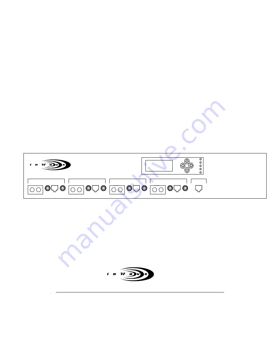
ioLink 4
CONSOLE
TX RX
1
TX RX
2
TX RX
3
TX RX
4


