background image

23

Chapter 2: Operation

2. 

Check for the 

Red

 light. Press the 

START / STOP

 key if it is not on.

3. 

Press the 

Test Cut

 key for one second. The plotter will cut a 

small test pattern consisting of a circle within a square.

4. 

Adjust the force and blade exposure up or down with the 

Force


knob and the blade foot. Repeat the test cut until the desired 

line quality is obtained. 

See the section on 

Cutting a Sign

 for 

details on adjusting force and blade exposure.

5. 

Successive test cuts automatically align to the left of the last test cut.

6. 

If the 

Test Cut

 key is pressed for three seconds the plotter will 

cut a 1.9 in. x 7.1 in. pattern.

Repeat

The SmarTrac nearly 1 megabyte of data in buffer memory so that 

you can use the 

Repeat 

key to create additional copies of a graphic 

without having to resend the file. The signcutter must be in 

STOP


mode (red LED) in order to use the this key.
Since the SmarTrac begins cutting or plotting at the current blade 

location in 

STOP

 mode, reposition the blade or pen first (using the 

Arrow

 keys) before pressing the 

Repeat

 key.

Several issues affect the repeat function and the data stored in memory:
1. 

If the file exceeds the capacity of the buffer, the 

Repeat

 function 

is disabled. 

2. 

Your graphic will remain in memory until you reset the origin, 

send another file, or update settings with the 

Update Display


function. (

Update Display

 is described later in this chapter.)

The Ioline Control Center

The Ioline 

Control Center

 is a utility program that does three things:


Allows adjustment of settings to tailor output from the computer.


Sends completed cut files to the signcutter. (To make design 

changes to the file, you must use the design software.)


Includes several diagnostic tests for troubleshooting.

If an origin is not set between 

files, two possible unintended 

results can occur: if the combined 

cuts do not exceed the buffer, 

Repeat

 will cause them all to 

be recut or, if the combined files 

exceed the buffer size, 

Repeat


will be disabled.

Note

To avoid communication port 

conflicts, do not simultaneously 

run more than one application 

that is communicating with the 

plotter.

Note

The design software may override 

the 

Control Center

 settings. 

Check to see if it has by pressing 

the 

Update Display

 button be-

fore and after a cut is completed. 

If the settings change, use the 

design software to modify cutting 

parameters.

Note

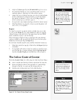
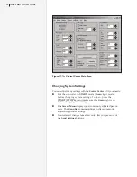
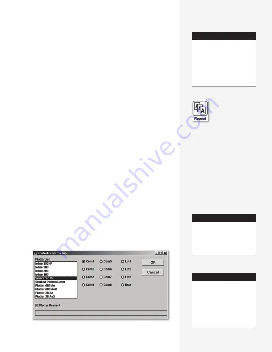
Figure 16. 

The 

Control Center Setup Screen

.

Summary of Contents for SmarTrac SC Series

Page 1: ...User Guide Ioline SmarTrac I S Series SC Series ...

Page 2: ...cutter and maintain it in proper working condition by following the instructions in this User Guide It is the respon sibility of the operator of the signcutter to follow all safety precautions and warnings that are described in this User Guide Ioline is not responsible for injuries that may occur as a result of unsafe operating proce dures Ioline is not responsible for substandard operational perf...

Page 3: ...User Guide Ioline SmarTrac I S Series SC Series ...

Page 4: ... 17 The Control Center Main Menu 24 Figure 18 Adjusting pinchwheel presure 31 Figure 19 Locking the idler pinchwheels off the platen 31 Figure 20 Installing the blade and blade foot in the holder 32 Figure 21 Installing the blade holder in the carriage jaw 32 Figure 22 When properly exposed the blade lightly scores the backing 33 Figure 23 Suggested settings for different materials 35 Figure 24 Pl...

Page 5: ...ling USB Drivers 17 Prepare to install 17 Windows XP Warning 17 Install Drivers 17 Find the COM Port 18 Setup the Software to use USB 19 Manually configure the USB settings optional 19 Power On 20 Installing Ioline Software and Manuals 20 Chapter 2 Operation Keypad Controls 21 START STOP 21 Arrow Keys 22 Set Origin 22 Speed 22 Force 22 Test Cut 22 Repeat 23 The Ioline Control Center 23 Changing Sys...

Page 6: ...sure 30 Locking the Pinchwheels Off of the Platen 31 Installing a Blade and the Blade Foot 32 Installing a Blade Holder or Pen 32 Adjusting Blade Exposureand Force 33 Adjusting Blade Exposure 33 Force Adjustment 34 Verification 34 Sending a Cut Plot File to the Signcutter 34 Pausing Cutting 34 Canceling a Cut 35 Suggested Settings 35 Guidelines for Plotting Pens 35 Cutting Long Signs 36 Cutting Sma...

Page 7: ...r 50 Gather the Calibration Data 50 Enter the Calibration Data 51 Calibrating the Sensor for Contour Cutting 52 Prepare to Calibrate the Sensor 52 Calibrate the Sensor 53 Service Support 55 Getting Help 55 Chapter 6 End Notes Customer Service 56 Your Comments Are Requested 56 Before you contact Support 57 The FCC WantsYou to Know 58 This booklet is available from 58 Glossary Index ...

Page 8: ...viii ...

Page 9: ...al adjustments are necessary turn off the signcutter and discon nect it from all power sources both the computer and the wall outlet Be careful with hair jewelry or loose clothing near the signcut ter They can become caught in the mechanical parts Never move the carriage by hand Use the Arrow keys and let the machine do it Keep hands away from the carriage when the signcutter is in operation The c...

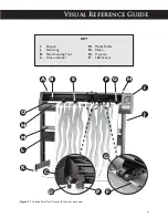
Page 10: ...r B Drive Shaft Marker C Carriage D Blade Holder E Idler Wheel F Drive Shaft beneath vinyl G Pinchwheel H Pinchwheel Lever KEY Figure 1 The Ioline SmarTrac I S cutter front view x G A B C H J E I L M N O F D K D C ...

Page 11: ...ce Guide Figure 2 The Ioline SmarTrac Contour SC cutter front view I Keypad J Stand Leg K Stand Leveling Foot L Cross member M Media Roller N Platen O Traverse P LED Sensor KEY xi A B E H J K I L M N O F G D P C G F ...

Page 12: ...rive Shaft Marker C Idler Wheel D Carriage E Blade Holder F LED Sensor G Pinchwheel H Drive Shaft KEY Figure 3 The Ioline SmarTrac SC 72 cutter front view A B J C K O P I N M See Detail 1 See Detail 2 See Detail 3 xii ...

Page 13: ...xiii K Stand Leg L Platen Leveling Foot M Stand Leveling Foot N Cross member O Platen P Traverse KEY L Detail 3 G H Detail 2 E F D Detail 1 ...

Page 14: ...n rear R Power Switch S Serial COM Port T USB Port U Power Cord KEY Q Figure 4 The Ioline SmarTrac Contour SC 72 cutter rear view Figure 5 Power and communications ports are located on the back of the right cover R U T S ...

Page 15: ...need to contact the manufacturer or your dealer Most design software provides drivers for Ioline signcutters If you need assistance with drivers contact Ioline customer service There is a specialized software program that comes with the signcutter called the Ioline Control Center This software utility enables you to adjust signcutter settings and perform system diagnostics The signcutter will cut ...

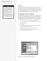
Page 16: ...er with either a USB or serial cable A serial cable is provided in the Accessory Kit Standard USB cables are widely available at computer stores or from Ioline The SmarTrac has a 9 pin male serial port receptacle If your com puter has a 25 pin serial port a 9 to 25 pin adapter is necessary Adaptors are inexpensive and available from computer stores or from Ioline After the cables are correctly con...

Page 17: ...to use the USB connection Note Windows XP Warning A warning may appear during Windows XP installation that the driver is not certified by Microsoft Please press the Continue Anyway button to continue with the installation Install Drivers 1 Turn on power to the Ioline equipment 2 The Add New Hardware Wizard window will appear Click on Next 3 Click in the circle next to Search for a suitable driver f...

Page 18: ...e System icon 3 In Windows 2000 and XP click on the Hardware tab then Device Man ager button In Windows 98SE click on the Device Manager tab 4 Double click on the Ports COM and LPT item to expand the list 5 Find the Ioline USB to UART Bridge Controller COMx item in the list Write down the COM port number shown in the label Use this infor mation when configuring software that communicates with the e...

Page 19: ...en the Windows Control Panel 2 Double click on the System icon 3 In Windows 2000 and XP click on the Hardware tab then De vice Manager button In Windows 98SE click on the Device Manager tab 4 Double click on the Ports COM and LPT item to expand the list 5 Right click on the Ioline USB to UART Bridge Control ler COMx item in the list then choose Properties 6 Click on the Port Settings tab and enter...

Page 20: ...f the Ioline Control Center and IQ Plot programs and electronic User Guides 1 Turn on the power to the computer and start Windows 2 Insert the Ioline CD ROM into the CD ROM drive usually D 3 Select the Start button 4 Choose Run 5 Type D SETUP substitute the correct letter if the CD ROM drive letter is not D and Click OK 6 Follow the instructions that appear on the screen 7 Consult the Operation ch...

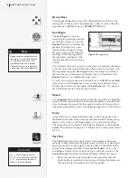
Page 21: ...between the computer and the signcutter If the START STOP key is pressed during cutting or plotting STOP mode the machine will stop when the current vector is finished The Arrow keys are active when in STOP mode When the START STOP key is pressed again START mode cutting will resume exactly where it stopped START mode Green light Arrow keys inoperable sign cutter online ready to receive instruction...

Page 22: ... speed or counterclock wise to decrease the speed Set the speed according to the type of cut ting and material being used See the Cutting a Sign section of this manual Force Adjust the force by using the Force knob on the front panel Turn the Force knob clockwise to increase the force exerted on the pen or blade See the section on Cutting a Sign for the recommended settings The range of force avai...

Page 23: ...tion and the data stored in memory 1 If the file exceeds the capacity of the buffer the Repeat function is disabled 2 Your graphic will remain in memory until you reset the origin send another file or update settings with the Update Display function Update Display is described later in this chapter The Ioline Control Center The Ioline Control Center is a utility program that does three things Allows...

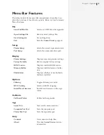
Page 24: ...nging system settings To do so press the START STOP key and make sure the Green light is on before changing any settings The Screen Menu displays most commonly adjusted param eters The Menu Bar contains utilities and less commonly adjusted signcutter settings Your selected changes take effect only after you press one of the Send Settings buttons Figure 17 The Control Center Main Menu ...

Page 25: ...tter Settings Displays current signcutter settings Factory Defaults Restore original factory settings ROM Version Displays installed ROM version Memory Buffer Displays installed memory buffer size Blade Status Displays whether or not the blade holder is installed Options Filtering Toggles Filtering on and off HPGL Setting Selects an HGPL language Install New Firmware Installs new firmware on the si...

Page 26: ...ory setting is 30 in 76 2 cm but the loop size is adjustable Disable Autoloop when cutting short pieces of vinyl or scraps Tangential Cutting When enabled the tangential cutting feature will carefully align the blade with the line segment before making each cut in the material Settings Enable Turns on the Tangential Cutting feature in the cutter after the Permanent button is pressed Length Determi...

Page 27: ...ay button be fore and after a cut is completed Check the plotter setup screens in the design software to make adjustments if necessary Note Pouncing Tag Board Default Length 40 mils 04 in 2000 mils Maximum Length 4000 mils 5000 mils Minimum Length 40 mils 50 mils Update Display Selecting this option will update all of the screen values with the current settings stored in the signcutter For example...

Page 28: ...imum 400 grams Default Minimum 10 grams Blade Overcut Blade Overcut is the distance the blade travels beyond the end of a cut Blade Overcut ensures that each cut actually reaches the point where one cut line meets and slightly overlaps another cut line This ensures that all of the pieces of the sign will be cut completely with no undercuts The factory set Blade Overcut is 10 mils This setting is i...

Page 29: ...orrect force can cause misalignment problems over the range of a long cut If the force is too high the material may skew 4 Prepare a large clean area to work Power On Turn on the computer and the signcutter The signcutter power switch is located next to the power cord on the back The carriage will move when the power comes on Keep hands and loose cloth ing away from all moving parts of the SmarTra...

Page 30: ...anging from the front of the machine against the edges of the material hanging from the back of the machine Pull downward on the material and square the edges so that they are parallel front and back Alternatively align the edge of the material with the edge of the material roll 6 While maintaining the material square and taut clamp the pinchwheels to the material by lowering the pinchwheel lever ...

Page 31: ...ting This will reduce ink smear ing if plotting with a heavy ink marker 1 Lift the idler pinchwheels off the platen with the pinchwheel lever 2 Press on the handles at the rear of the idler pinchwheel arm 3 Flip the locking clip into position with both thumbs Make sure that the clip is under the lower tabs 4 When the pinchwheels are lowered onto the platen the idlers will stay in the up position T...

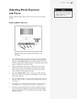
Page 32: ...y then turn the clamp screw until there is enough room to insert the blade holder or pen 2 If using a blade holder or plotter pen slip the flange into the slot in the carriage jaw If using a regular pen position the tip 1 10 inch off of the platen when the jaw is in the up position The signcutter can hold any pen with a maximum barrel diam eter of 7 8 in 22 mm 3 Tighten the clamp screw until the bl...

Page 33: ...hes the correct blade exposure from too little with no chance of having too much which could damage the blade 3 Press the START STOP button on the front panel until the LED is red Move the carriage until the blade is near the right edge of the material 4 Press the Test Cut key for one second The signcutter will cut a test sign There will be no cutting if the initial foot adjustment was correct 5 T...

Page 34: ...cuts to determine the cor rect settings before sending any files See the Adjusting Blade Expo sure and Force sections for more details Important Make sure that the carriage and material are in the proper position and that an origin is set by pressing Set Origin on the keypad LED is green Send the file directly from the design software following the direc tions in the documentation or From the Ioline...

Page 35: ... has determined guidelines for plotting with a plotter pen Refer to the Figure 24 for recommended settings for a variety of pen Material Thick ness mils Blade Offset mils Force2 grams Speed ips Accel eration grams Min Angle degrees Overcut mils Down Delay millisecs Amberlith Rubylith 1 45o 15 30 60 med 0 1 30o 0 5 0 50 Flock 15 Cobra 47 100 200 min 1 15o 10 0 Polyester Metalized 2 45o 15 100 140 m...

Page 36: ... downward 2 Build a material slide Cut two cardboard pieces the width of the stand and large enough to lean against the stand legs This prevents the material from going under the machine and get ting buckled with material from the other side 3 Check the material roll Place the roll of material to the right of the material cradle or media rollers Make sure the roll is tightly wrapped and even along...

Page 37: ... consuming back and forth and side to side movements Wear on the material backing as well as the vinyl is also decreased which will improve tracking The more complex the file the more difficult the problem 10 Use the Paneling feature in the design software Paneling will restrict the length of any X axis move Ioline suggests a Panel Size of 10 to 20 inches With most signmaking software the Paneling f...

Page 38: ...e also required 1 Select Pounce in the Ioline Control Center Make sure that Tag Board Cutout is turned OFF Put the signcutter in START mode green LED on Update the signcutter with the Send Set tings temporary or permanent buttons 2 Slide the paper roll onto a media roller use the roller as an axle Ioline does not recommend using two media rollers to cradle paper rolls 3 Enable Autoloop or create a...

Page 39: ...or create a service loop of material 4 Install a blade holder in the carriage 5 Perform test cuts to establish blade exposure and Force set tings See the section Adjusting Blade Exposure and Force for the proper procedure Most tag board cuts are made at or near maximum force 400 grams Check the Control Center for the maximum force setting Adjust as necessary See the Suggested Settings in Figure 23...

Page 40: ... pad so that the keypad light turns green 3 Open the Ioline Control Center software 4 Find the Tangential Cutting box on the main screen 5 Check the box next to Enable Press Permanent in the Send Settings to Cutter window 6 Perform a test cut on the machine See Cutting a Sign earlier in this chapter to learn about test cuts 7 Adjust parameters as necessary The settings are explained below Make sur...

Page 41: ...ally when heat is used to cure the ink or apply films These processes cause the image to expand and contract and might affect accuracy The following condi tions are required for successful regis tration cutting with an Ioline SmarTrac Contour cutter 1 The background material is white 2 Four registra tion marks are printed in the corners of an encompass ing rectangle around the pre printed image s I...

Page 42: ...alled in the carriage The cutter is cali brated for the blade holder at the factory Procedure 1 Load the pre printed material into the cutter and verify that material movement is as straight as possible 2 Center the sensor light over the first registration point and press the Set Origin key on the keypad The first registration point R1 is nearest the right end of the cutter and the front edge of the...

Page 43: ... details 2 Start the Ioline Control Center Select Test Communication Test from the menu bar at the top of the window 3 Turn on the signcutter while holding down the Test Cut key on the keypad Hold down the Test Cut key until the signcutter beeps and the light flashes three times The signcutter is now in Test Mode 4 If testing the serial COM port press the START STOP key on the signcutter and verify...

Page 44: ...nd of the tes to exit Test Mode If this test fails the signcutter port is faulty Testing the Computer Serial Port The diagnostic module is required for this test 1 Connect the diagnostic module directly to the COM port on the computer If the computer COM port has a nine pin connector use a 9 pin to 25 pin adapter between the COM port and diag nostic module 2 From the Control Center main menu selec...

Page 45: ... The plot does not start at the correct point on the material Cause 1 You have not set an origin 2 The origin selected in your soft ware is different than the one you selected on your plotter Solution 1 Select an origin 2 Select origins in the software and on the plotter that coincide usually lower left which is the right side of the plotter See Figure 4 The plot does not repeat when pressing the ...

Page 46: ...on The design does not weed cleanly Cause 1 Blade Force is too low 2 The blade is dull or broken 3 The Blade Overcut is too low 4 The Offset is incorrect Solution 1 Increase Blade Force 2 Replace the blade 3 Use a higher Blade Overcut value 4 See the Blade Offset section Poor tracking Cause 1 Pinchwheels are positioned over a bearing e g a smooth section of the drive shaft 2 Blade Force is too hig...

Page 47: ...icates with the signcutter over a network it is common for LPT 1 to be captured meaning the data is redirected to the network instead of flowing out of the parallel port on the back of the computer Ending the capture will allow data to flow normally from the computer to the plotter 1 Click the START button select Settings and then click Printers to open the Printers window 2 Right Click the printer ...

Page 48: ...ick the Device Manager tab 3 Remove the parallel port by clicking Ports selecting the port and clicking the Remove button 4 Shut down Windows 5 Restart or Reset the computer 6 Enter the PC BIOS setup This is usually done by hitting the DEL key or ESC key during the boot sequence Consult the computer manuals or contact the manufacturer for more infor mation about entering BIOS setup 7 Find the para...

Page 49: ...djustable blade foot by unscrewing it counter clockwise 2 Remove the old blade with a pair of needle nose pliers and discard it 3 Slide the new blade into the blade until it bottoms out The blade should spin freely 4 Screw the foot onto the blade holder clockwise Stop just be fore the blade tip emerges The blade tip is sharp and fragile Be careful when handling it Caution 5 Perform test cuts as de...

Page 50: ...or larger models and a minimum of 48 in long Install a blade holder use vinyl material or pen use paper material in the carriage Enable Autoloop or manually create a service loop of material 3 Move the carriage and material with the Arrow keys so that the blade or pen is about one inch from both the right and front edge of the material Set an origin See the Operation chapter for more details on pr...

Page 51: ... X2 39 700 in The sum is 79 450 in 39 750 in 39 700 in 79 450 in The average is 39 725 in 79 450 in 2 39 725 in The X calibration value is the average 39 725 in Enter the Calibration Data 1 Enter the measured values in the boxes in the Calibration win dow Make sure the SmarTrac is in START mode green LED Select the Set Calibration button 2 The signcutter will send the calibration values and the ne...

Page 52: ...ion to gener ate the square Make sure that there is at least a margin of 3 inches from each edge of the material to the edges of the box Printing the square in the center of a standard sheet of white paper is acceptable Make sure to carefully mea sure the square after printing to ensure that it is exactly 1 cm 1 cm 1 cm Figure 33 Print and measure a 1 cm black square on a white background Sensor c...

Page 53: ...e tip is lined up See the Figure 35 5 Press the Set Origin button on the keypad and ensure that the keypad light is Green Calibrate the Sensor 1 Open the Ioline Control Center A shortcut is available in Start Ioline Figure 36 The Control Center Calibration window 2 In the Menu Bar choose Calibrate Calibrate Plotter Figure 36 3 Press the Sensor Calibration button at the bottom of the window 4 Ensur...

Page 54: ...egistration cuts to verify that alignment is correct If it is not check that the black box is exactly 1 cm then repeat the procedure again Contact Ioline Customer Service if calibra tion is unsuccessful Figure 37 The Small Sensor Calibration window ...

Page 55: ...this product not specifically described in this manual must be authorized in writing by Ioline Customer Service You may obtain service by calling or faxing Ioline Customer Service The technicians will help you determine the nature of the problem If factory repair is necessary you will receive a RMA Re turn Material Authorization Please gather the information indicat ed on the next page before conta...

Page 56: ...ou need assistance with an Ioline prod uct contact your local dealer or Ioline authorized service center You may also contact Ioline Customer Service Department Monday through Friday 7 00 A M 5 00 P M U S Pacific Time Voice 1 425 398 8282 Fax 1 425 398 8383 support ioline com www ioline com Your Comments Are Requested Ioline Corporation is interested in comments on our documentation and products Pl...

Page 57: ...l used Type of Computer Type of design software New software or peripherals Service history Before you contact Support Please gather the following information about your printer before contacting Ioline or your dealer for technical support Look for the serial number above the power switch on the back side of the right cover ...

Page 58: ... computer and receiver are on different branch circuits If necessary consult the dealer or an experienced radio television technician for additional suggestions How To Identify and Resolve Radio TV Interference Problems a booklet published by the Federal Communications Commission is a helpful reference Please contact the FCC to request a copy www fcc gov Document stock number 004 000 00345 4 This ...

Page 59: ...rink or move back to its original thick ness Cast Polyvinyl chloride PVC sheeting formed by spreading a molten vinyl mixture on a carrier sheet or web and then baking at high temperatures to re move solvents and fuse the remaining material into a film Cast film is usually thinner and more expen sive than calendered vinyl Control Panel Panel on the right side of the ma chine where primary plotter fun...

Page 60: ...de material flat during cutting J K Keypad Panel on the right side of the machine where primary plotter functions are accessible Also called the Control Panel L M Mil Thousandths of an inch or milliinches For example 75 mils is the same as 075 inches 1 mil is equal to 025mm Minimum Angle This is the minimum angle for which the machine will perform a Blade Steering Arc N O Offset The distance the ti...

Page 61: ...into which a design is cut When a stencil is placed on another substrate and paint or ink is applied the image represented by the cut out portion of the stencil is printed on the substrate below it T Tag Board A heavy paper usually 150 pound that is used in the apparel industry for cutting patterns and stencils Tangential Cutting When enabled the tangential cutting feature carefully aligns the bla...

Page 62: ...62 62 Ioline SmarTrac User Guide This page intentionally left blank ...

Page 63: ...libration box 51 52 53 54 Calibration Box 51 Cam slot 31 Cancel a job 35 Carriage x xi xii xiii 16 20 22 26 27 28 29 30 32 33 34 39 42 47 50 53 59 60 61 Carriage rail SeeTraverse Cast 59 Communication Conflicts 23 Parallel 60 Parallel port 47 Serial xiv Setup within the design software 16 Setup within the Ioline Control Center 16 25 USB xiv Setup 19 CommunicationTesting 43 43 44 Computer 57 COM Por...

Page 64: ...5 Flange 60 Font 60 Force 22 23 28 31 33 34 35 37 39 60 Adjusting 33 34 Friction feed 60 G Green light mode See START mode H Help x 22 25 36 38 43 55 57 59 60 High Force Position 31 HPGL 25 46 60 HPGL Setting 60 I Idler wheel x xii 60 Position 30 Installation 16 18 Ioline Corporation x 56 IQ Plot 20 J Jaw 32 52 53 K Keypad v xi 21 59 60 Arrow keys 21 Controls 21 23 Force 22 Repeat 23 Set Origin 22...

Page 65: ...er 60 Plotter settings 25 PLT 25 60 Pounce vi 26 38 39 61 Blank value 27 Cut value 27 Pounce pattern 61 Pouncing Cut 38 Power cord xiv Power switch xiv 57 Q R Radio frequency 58 Red light 47 Red light mode See STOP mode Reflectives 31 40 Registration marks 41 42 59 61 Registration tool 52 Repair 55 56 Repeat v 22 23 43 45 51 Resolution 61 Roll feed 61 ROM version 25 S Safety x ix Sandblast 28 30 31...

Page 66: ...ents 15 System settings Adjusting 23 Permanent 27 Saving 25 Suggested settings 35 Temporary 27 T Tag board 27 35 38 39 61 Tangential cutting 40 61 Tech Support 56 Test cut v 22 23 27 33 34 36 38 43 44 Throughput 61 Traverse xi xiii Troubleshooting 45 48 Communication Conflicts 23 Computer Port Test 25 Diagnostic tests 23 Plotter Port Test 25 Radio TV interference 58 Radio or TV interference 58 Seri...

Reviews: