InWin IW-RS448-05 User Manual Download Page 26


23 

■ 

Hot-Swappable HDDs 

-    Hot-swap your HDDs. No need to shut down your system for HDD installation 

and/or replacement when an HDD failure is present or while adding a new HDD to 
the system. 


 Cascading 

-    There is a cascading port on the Expander for cascading to another Expander for 

expanding disk space. 


InWin High Density 4U Storage Server system shares the same InWin RSxxx-03 (04) 
Enclosure Management User Interface. Please use the following image of RS-212-03p 
as an example. The actual product's model will appear when the program is executed.


4.2


UART Usage 

4.2.1


UART configuration 

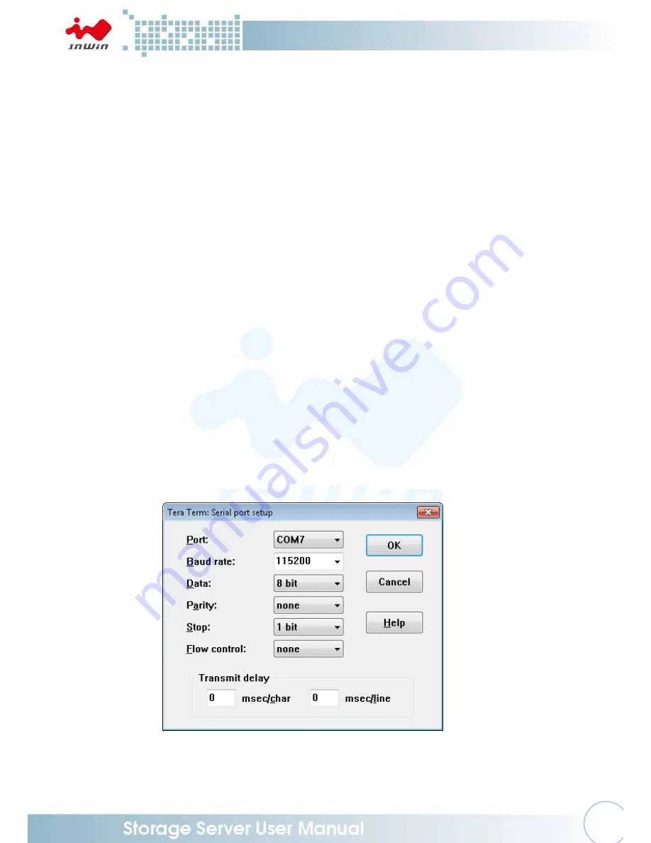
RS-232 UART port on the expander module provides a serial connection for users 

to manage Terminal applications such as: Tera Term, Hyper Term…etc. 


To manage Expander through the UART port, the settings below must be properly 
configured to enable its function. 
 
Baud Rate 

: 115200 

Data 


: 8 bit 

Parity   

: None 

Stop Bit  

: 1 bit 

Flow Control : None 


When connected, there is a display prompt on the Terminal interface screen, then users 
can start typing CLI commands.   

Summary of Contents for IW-RS448-05

Page 1: ...IW RS448 05 User Manual...

Page 2: ...Removing and Installing the Fan Module 11 2 2 1 Removing the Fan Module 11 2 2 2 Installing the Fan Module 11 2 3 Removing and Installing the PSU Module 12 2 3 1 Removing the PSU Module 12 2 3 2 Insta...

Page 3: ...e Introduction 21 3 1 SAS 12G Backplane for 7mm SSD 21 3 2 HDD Backplane 21 4 SAS Expander Board Introduction 22 4 2 UART Usage 23 4 2 1 UART configuration 23 4 2 2 System Revision 24 4 2 3 System Mon...

Page 4: ...and away from sources of heat including direct sunlight and radiators It should be kept away from sources of vibration or physical shock The space should be accommodated with a properly grounded wall...

Page 5: ...er carefully and plug the jumper to cover the jumper pins on the backplane Once you need to remove the jumper grip the jumper and carefully pull without squeezing CAUTION To avoid damage and maintain...

Page 6: ...gh efficiency redundant Watt 1200W Indicator Power LED LAN1 LAN2 LED System LED ID LED HDD LED Front Control Panel Power On Off Reset NMI ID SW USB 3 0 x 1 Backplane Mini SAS HD 12Gb s with expander C...

Page 7: ...4 1 Product Introduction 1 1 Box Contents...

Page 8: ...is opened Top cover High efficiency redundant power supply 48x top load hot swap LFF HDD bays with built in Cable Management chain Front controls and indicators ATX or EEB Motherboard Blower fan Max 4...

Page 9: ...e 5 Drives Status LEDs for Bays 1 48 Refer to the table below 6 Status LED Red Solid on System maintenance PSU fan malfunction 7 LAN LED LAN1 LAN4 8 USB 3 0 Connector N A USB devices connection 9 Draw...

Page 10: ...e 1 Default primary power supply module 7 Power Module 2 Backup power supply module 8 System I O depends on M B specifications The I O shield is dependent upon your choice of motherboard and is provid...

Page 11: ...tools NOTE Do not leave the HDD drawer open for more than 1 minute to prevent overheating 2 1 1 Open the HDD Drawer Step 1 Unlock the keylock and loosen the thumbscrews of the drawer Step 2 Pull the...

Page 12: ...clicks Fully insert the HDD into the tray from the correct disk port orientation Step 3 Align the HDD screw holes and plug in the pins on the side of each tray Keep the tray pins against the HDD scre...

Page 13: ...ach drive tray Open the drive tray cover and pull it outward as a handle Step 2 Pull up the tray until it clicks Pull the hard drive out carefully Step 3 Lower the drive tray back Release the latch to...

Page 14: ...Fan Module Step 1 Press the clip and rotate the lever of the fan module outward Step 2 Pull out the fan module from the fan slot Step 1 Step 2 2 2 2 Installing the Fan Module Step 1 Push the fan modul...

Page 15: ...PSU modules only please do not attempt to insert any other module brands 2 The two PSU modules output wattage must be the same 2 3 1 Removing the PSU Module Step 1 Loosen the thumbscrew of the power...

Page 16: ...DD drawer Please refer to 2 1 1 Step 2 Loosen the thumbscrews and the screws of the SAS expander module cover then remove the cable management cover Step 3 Remove the cable from the SAS expander modul...

Page 17: ...o position and tighten the thumbscrew Step 3 Connect the cable to the disk expander module Step 4 Push the cable management cover back to its original position Tighten the thumbscrew and secure the sc...

Page 18: ...5 screws red circles securing the top cover and fan modules Step 2 Slide the cover towards the rear then lift the top cover and fan modules off the chassis Step 3 Remove the mylar cut outs that are co...

Page 19: ...ED Front Control Panel and Front USB Refer to your motherboard s User Guide for pin functions and locations then plug the connectors to the pins on the motherboard to activate the functions USB3 0 M B...

Page 20: ...nt IO Indication ID LED ID LED Green Black Chassis ID Button with LED ID Switch ID SW Blue Black Chassis ID Button with LED LAN1 LED LAN1 Grey Black LAN LED LAN2 LED LAN2 Red Black LAN LED SYSTEM LED...

Page 21: ...stall the rails on the cabinet or chassis rack according to the rail type you ordered 2 7 2 Fixed Rail Blades 2 7 2 1 Installing the Fixed Rail blades to the Rack Step 1 Prepare the rack posts with sq...

Page 22: ...y Handle with Care Use and secure the removable handles while transporting At least two people are required for the following operation Step 2 Place the enclosure into the rack carefully Align the fix...

Page 23: ...20 Step 2 Step 3 Front Rear Rear Front Front Rear Rear Front...

Page 24: ...ory only LEDx Bi Color LED Blue Power Access Red Locate Failure D1 MCU heartbeat CN5 Mini SAS HD connector SAS uplink PWx Standard Berg connector 3 2 HDD Backplane Location Description PW1 BP Power Co...

Page 25: ...anel Signal Connector EFN1 Expander FAN Connector LED11 12 13 LED11 13 JS1 JS3 PHY LED LED01 SAS Expander Heartbeat LED JS1 JS3 JS1 JS2 Internal MINI SAS HD Uplink JS3 Internal MINI SAS HD Downlink JM...

Page 26: ...Please use the following image of RS 212 03p as an example The actual product s model will appear when the program is executed 4 2 UART Usage 4 2 1 UART configuration RS 232 UART port on the expander...

Page 27: ...24 4 2 2 System Revision To check the Expander revision type rev and sys rev to get the expander information such as Vendor ID Firmware Version SAS Address etc...

Page 28: ...25 4 2 3 System Monitoring To monitor the status of the enclosure s sensors such as Temperature and DC power amplitude type command sys in the UART...

Page 29: ...26 4 2 4 Disk PHY Status To monitor the SAS PHY status type Phyinfo or sys hdd to check Users can check the disk link status by using these commands...

Page 30: ...the Expander Be sure these binary files are available in the host before conducting firmware updates 1 SAS Expander Operation Firmware 2 SAS Expander MFG CFG binary The updated firmware does not take...

Page 31: ...e transfer to the SAS Expander F The Terminal interface will then start the firmware transfer G After the firmware transfer is completed type the reset command in the Terminal interface screen or powe...

Page 32: ...er cycle the system to activate the new firmware 5 Compatibility Lists To reach the best performance and avoid system failure InWin strongly recommends users to choose the components from InWin s comp...

Reviews: