background image

30



On left panel, click on Device Manager.



On right panel, double-click on Ports.



A list of active COM ports will be displayed. Note the COM number 
assigned to the adapter you just installed. 

For example: 



Close Manager.

• 

Connect to the sensor.

• 

On the Aqua4Plus software, select the COM port noted above. (If you do not 
see your new COM port in the dropdown box, open the Communications dialog 
box from the Options menu. Increase the Highest COM port number, up to a 
maximum of 15.)

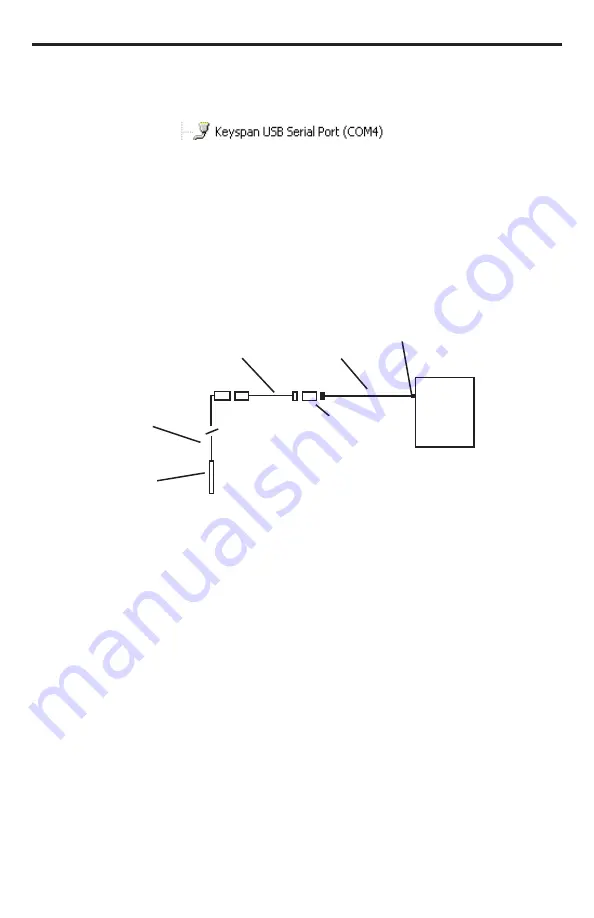
Connection using a USB to Serial Adapter

Interface 

Cable

PC or Laptop

Computer

USB Port

USB-to-Serial 

Adapter

RS232/RS485

Adapter

Sensor

Sensor

Cable

Summary of Contents for AquiStar T1

Page 1: ...AquiStar T1 T1R Temperature Sensor INSTRUCTION MANUAL ...

Page 2: ...ommands 11 Calibration Register Definitions 13 T1R Recording Sensor Operation 14 Connecting External Power 14 Connecting the T1R to a Computer 14 Installing the Aqua4Plus Software 15 Collecting Data 15 Field Calibration 18 Technical Specifications 19 Dimensions and Specifications 19 Direct Read 21 Setting Units for Direct Read 21 Reading Via Modbus RTU 22 Reading Via SDI 12 24 Changing Batteries 2...

Page 3: ...er No part of this manual may be reproduced or transmitted in any form or by any means electronic or mechanical including photocopying and recording for any purpose without the express written permission of the manufacturer 1997 2014 Instrumentation Northwest Inc Registered trademarks and trademarks belong to their respective owners ...

Page 4: ...ther two internal AA batteries or an external 6 to 15 VDC power supply The unit is programmed using INW s easy to use Aqua4Plus control software Once programmed it will measure and collect data on a variety of time intervals The T1R can be used as a stand along unit or network with other INW AquiStar Smart Sensors as well as with many data loggers and SCADA systems using Modbus RTU or SDI 12 Initi...

Page 5: ...the tension off the connectors Don t allow the device to free fall down a well as impact damage can occur Don t bang or drop the device on hard objects Do handle the device with care Do store the device in a dry inside area when not in use Do install the device so that the connector end is kept dry ...

Page 6: ...4 5 5 Pin Connector White Purple Yellow Brown Blue Shield 12 VDC Vaux Modbus D Modbus D SDI 12 Not used Ground 1 2 3 4 5 5 Pin Connector White Purple Yellow Brown Blue Shield 12 VDC Vaux Modbus D Modbus D Digital I O Not used Ground 1 2 3 4 5 5 Pin Connector For Modbus with firmware lower than 2 0 with 5 pin connector For Modbus with firmware 2 0 or higher with 5 pin connector For SDI 12 with firm...

Page 7: ...her than water Maintenance Sensor There are no user serviceable parts If problems develop with sensor stability or accuracy contact INW If the sensor has been exposed to hazardous materials do not return it without notification and authorization Cable Cable can be damaged by abrasion sharp objects twisting crimping or crushing and pulling Take care during installation and use to avoid cable damage...

Page 8: ...of which may have its own ground problems with noise signal interference and erroneous readings may be noted This is caused by a condition known as a Ground Loop Because of natural re sistance in the earth between the grounding points current can flow between the points creating an unexpected voltage difference and resulting erroneous readings The single most important step in minimizing a ground ...

Page 9: ...ect Modbus Read Output 32 bit IEEE floating point SDI 12 Output ASCII Internal Math 32 bit floating point Operating Temperature Range1 5 C to 70 C Storage Temperature Range 40 C to 80 C POWER Operating Voltage 9 16 VDC Over Voltage Protection 24 VDC Power Supply Current Active 3mA avg 10mA peak Sleep 150 μA Electomagnetic Transient IEC 61000 4 3 4 4 4 5 4 6 Protection TEMPERATURE Element Type Digi...

Page 10: ...erature offset 40231 32 T_ZeroSlope Factory calibration Temperature slope 40237 38 T_mUnits Temperature Units Conversion slope 40239 40 T_bUnits Temperature Units Conversion offset Factory calibration values are set at the factory Writing to Factory Calibration registers will void calibration Field calibration values can be set by user If set these values will be applied to readings before values ...

Page 11: ...er is returned 3 The sensor turns on the analog portion begins sampling and begins putting the new values in the registers 4a If auto enable is set to a positive value w the sensor stays awake for w seconds sampling and moving values into the registers all the while and then goes to sleep 4b If auto enable is set to zero the sensor immediately goes to sleep after putting the reading in the registe...

Page 12: ... Request measurement aM a0023 cr lf request temperature voltage measurement aD0 a 0 25 0000 12 0512 cr lf read null temperature C voltage V aM2 a0021 cr lf request temperature measurement aD0 a 25 0000 cr lf read temperature C aM3 a0021 cr lf request power supply voltage measurement aD0 a 12 0512 cr lf read power supply voltage V aM4 a0ttt4 cr lf request averaged data ttt depends upon programmed a...

Page 13: ... aCC a00203 cr lf request temperature voltage measurement aD0 a 0 25 0000 12 0512 crc cr lf read null temperature C voltage V aCC2 a00201 cr lf request temperature measurement aD0 a 25 0000 crc cr lf read temperature C aCC3 a00201 cr lf request power supply voltage measurement aD0 a 12 0512 crc cr lf read power supply voltage V aCC4 a0ttt04 cr lf request averaged data ttt depends upon programmed a...

Page 14: ...000000E 00 14 T_Offset Factory Temperature Cal Offset 0 000000E 00 15 T_ZeroSlope Factory Temperature Cal ZeroSlope 0 000000E 00 18 T_mUnits Temperature units conversion slope 1 000000E 00 19 T_bUnits Temperature units conversion offset 0 000000E 00 Factory calibration values are set at the factory Writing to Factory Calibration registers will void calibration Field calibration values can be set b...

Page 15: ...15 mA Connect to Vaux pin 1 white and Ground pin 5 blue or contact INW for auxiliary power supplies Connecting the T1R to a Computer Connect the T1R to your computer s USB port as shown below Drivers and instructions come with the adapter For alternate connection options see Alternate Connection Options Section Connect the sensor to your PC using INW s USB to RS485 adapter See Appendix C for alter...

Page 16: ...DI 12 interfaces allowing you to do the following Read a T1R via the Modbus protocol using your own software Read a T1R via SDI 12 protocol Display readings from a T1R on a panel meter If you want to use one of these methods please see Direct Read Section or contact INW for more details Collecting Data Following is a brief overview on using Aqua4Plus to collect data Please refer to the Aqua4Plus I...

Page 17: ...ession profile Click the Start button to save the session to the sensor and begin recording Using the Session Profile Window describe the test steps for your particular test Retrieving Data from the Sensor Datalogger Click on the session you want to upload Click the tool button Select a file location Click Save Click Start Select the data session you are ready to upload ...

Page 18: ...on to view data as a graph Navigate to the desired file then click the Open button If the File Open box does not appear click the File Menu then select Open The File Display window displays your data in a tabular format The Graph Window displays your data on an X Y coordinate graph ...

Page 19: ... a field calibration from time to time One Point Calibration Computing Calibration Value Place sensor in water Allow time for sensor to reach thermal equilibrium Using an accurate alternate measuring device measure the temperature of the water In the Ref deg box for the first point enter this temperature Click first Measure button When readings have stabilized to your satisfaction click the OK but...

Page 20: ...bration Values Click the Apply button to apply calibration values The computed m and b values will be transferred to the calibration fields Click OK to save the values to the sensor Technical Specifications Dimensions and Specifications GENERAL Length 10 725 27 24 cm cabled 10 475 26 61 cm cableless Diameter 0 75 1 9 cm Weight 0 8 lb 0 4 kg Body Material Acetal 316 stainless steel or titanium Wire...

Page 21: ...s up to 255 File Formats xls csv a4d TEMPERATURE Element Type Digital IC on board Accuracy 0 2 C Resolution 0 06 C Operating Temperature Range 5 C to 70 C Storage Temperature Range1 20 C to 80 C Units Celsius Fahrenheit Kelvin 1 Storage without batteries POWER Internal Battery 2x1 5V AA alkaline2 Auxiliary Power 12 VDC Nominal 6 15VDC Range Exp Alkaline Battery Life 18 months at 15m polling interv...

Page 22: ...rature Degrees Celsius However you can select from a variety of units for direct read measurements If you want to change to different units for example degrees Fahrenheit for temperature set these units using Aqua4Plus Click on the Configure menu and then select Advanced From the flyout menu select Direct Read Units On the popup box click the down arrow next to the Temperature box and then select ...

Page 23: ... will not be able to talk to it with Aqua4Plus until you change the baud rate for Aqua4Plus as follows Click the Options menu and then select Baud Rate On the popup box click the down arrow select the baud rate you need and then click OK The current Aqua4Plus baud rate is displayed in the lower right corner of the main Aqua4Plus window Taking Measurements Reading Registers Read measurements using ...

Page 24: ...ause of this the first reading you get will be old If you are taking readings at intervals of less than 10 seconds simply ignore the first reading all remaining readings will be current On the other hand if you are taking readings at intervals of greater than 10 seconds take a reading ignore it wait one second take another reading Record this second reading Data Format The data is returned as 32 b...

Page 25: ...sssssssss cr lf note 2 1 will change to reflect current firmware revision ssssssssss device serial Acknowledge Active Address Query a a cr lf a cr lf Change Address a A b b cr lf change address to b Request measurement a M1 a 0021 cr lf request temperature measurement a D0 a 22 0512 cr lf read temperature Request measurement with CRC a MC1 a 0021 cr lf request temperature measurement with CRC a D0...

Page 26: ... sensor slipping out of the clamping device If the sensor body is slippery or you are unable to grip it hard enough to twist try a piece of rubber cabinet liner for additional friction Opening the Housing There is a black compressible square ring near the top of the sensor This ring acts as a spring to lock the cable in This needs to be compressed in order to allow removal of the top cap Once this...

Page 27: ...ith Vise recommended method Cabled Sensor 1 If possible use a set of soft jaws as shown to prevent marring the surfaces of the top cap assembly 2 Place the sensor in a vise clamping gently on the swaged area You do not need to clamp the vise very hard Continue to Removing the Housing on the next page Cableless Sensor 1 If possible use a set of soft jaws as shown to prevent marring the surfaces of ...

Page 28: ... not grab the knurled diameter 2 Find a hard edge and place the tips or side of the jaws of the pliers onto this edge as shown This will allow you to press down with your weight to compress the square ring Continue to Removing the Housing below Cableless Sensor 1 Leave the cableless cap on in order to protect the pins inside 2 Grasp the pliers on the knurled area tightly being careful to avoid gra...

Page 29: ...ng into the cutaway on the circuit board with your thumb to protect it while being installed back into the housing 5 Rotate the top cap assembly into the opening in the housing being very careful not to nick or pinch any wires 6 Gently press down until the assembly stops and then twist it into place It will click in and decompress the gasket when it is fully engaged Pull wires gently to the side t...

Page 30: ... from many electronics and computer stores as well as numerous sites on the Internet INW has tested and recommends the Keyspan USA 19HS It is available from INW as well as from many sites on the Internet Install as follows Plug into USB port Install the drivers provided with the particular unit Determine the port number to which the adapter is assigned Right click on My Computer From the popup men...

Page 31: ...nager Connect to the sensor On the Aqua4Plus software select the COM port noted above If you do not see your new COM port in the dropdown box open the Communications dialog box from the Options menu Increase the Highest COM port number up to a maximum of 15 Connection using a USB to Serial Adapter Interface Cable PC or Laptop Computer USB Port USB to Serial Adapter RS232 RS485 Adapter Sensor Senso...

Page 32: ...31 Reordering Information For sales service offices please contact Instrumentation Northwest Inc www inwusa com 800 776 9355 ...

Page 33: ...ltered or repaired by the Buyer without prior written approval by the Seller all warranties are void Equipment and accessories not manufactured by the Seller are warranted only to the extent of and by the original manufacturer s warranty THE FOREGOING WARRANTIES ARE IN LIEU OF ALL OTHER WARRANTIES WHETHER ORAL WRITTEN EXPRESSED IMPLIED OR STATUTORY IMPLIED WARRANTIES OF FITNESS AND MERCHANTABILITY...

Page 34: ... 425 822 4434 FAX 425 822 8384 info inwusa com INW 1997 2014 by Instrumentation Northwest Inc All rights reserved Instrumentation Northwest and INW are trademarks registered with the U S Patent Trademark Office Doc 9B0009r4 04 14 14 PN 6D292 NI ...

Reviews: