background image

14

Rev 05

Quality
Assurance

Chapter 3 - Quality Assurance

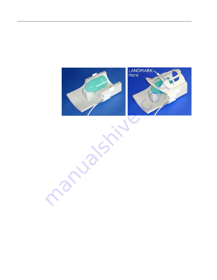
Remove the coil top and place the phantom positioner (part number 102485) and
the phantom (part number 102690) as shown in the figures below.  Replace the
coil top.

Connect the coil to the system as detailed in Chapter 2, "Connecting the cable."
Landmark on the the phantom through the small window in the top of the coil.

Follow the proceedure found on the next 8 pages.

Summary of Contents for Invivo 500082

Page 1: ...1 Rev05 Operator sManual Model HNC 63 INT Neurovascular Array Coil for the Philips Intera 1 5T MRI System Part Number 500082...

Page 2: ...software and or hardware may affect compatibility Prior to upgrading your MR system please contact the Invivo Customer Service Department to discuss coil compatibility issues Failure to do so may voi...

Page 3: ...lable through Philips Medical Systems Contact your Philips Representative for this software patch Software releases after 8 1 1 do not require the software patch A SYNERGY MULTICONNECT device is requi...

Page 4: ...ure the housings together and ensure proper electrical connections between anterior and posterior housings With latches in the open position the anterior housing may be lifted from the posterior housi...

Page 5: ...on the Patient Table 9 Positioning the Patient 10 Synergy MultiConnect SMC 11 Connecting the Cable 12 Left Side Patient Interface Control Unit PICU 13 Right Side Patient Interface Control Unit PICU 13...

Page 6: ...ical spine anterior neck and vasculature of the head and neck to the aortic arch The operator should be aware of the following contraindications for use related to the strong magnetic field of the MR...

Page 7: ...ved before scanning because it may contain metal flakes which can cause skin and eye irritation Permanent eyeliner tattoos may cause eye irritation due to ferromagnetic particles Patients who work in...

Page 8: ...ith the cable pins and connector may damage the connector and affect coil or system performance Please verify that connector and pins are not damaged before use The coil and accessories require specia...

Page 9: ...y on the patient support With the anterior coil housingremoved centertheposteriorcoilhousingonthepatientsupportatthemagnet end of the patient support Position support pad flush with the end of the HNC...

Page 10: ...d seat the RF connector pins while the flat mating surfaces meet Secure the latches on each side of the housing Slide the viewing mirror if necessary for patient viewing Use the window on the anterior...

Page 11: ...ase 8 1 1 software requires a Synergy MultiConnect patch to enable this coil to be recognized by your system Contact your Philips representative to receive this software patch Software releases above...

Page 12: ...For systems with PICU on left side of magnet transfer SMC connector across table to the PICU IMPORTANT For SMC cable to reach PICU on left side of magnet patient will need to be in position within the...

Page 13: ...ach SMC connector to PICU Example above is left side PICU Attach SMC connector to PICU Example above is right side PICU Right Side Patient Interface Control Unit PICU Left Side Patient Interface Contr...

Page 14: ...part number 102485 and the phantom part number 102690 as shown in the figures below Replace the coil top Connect the coil to the system as detailed in Chapter 2 Connecting the cable Landmark on the t...

Page 15: ...Flipangle deg 20 00 TR userdefined ms 15 00 HalfScan no Waterfatshift maximum Shim no Run a SURVEY scan using the parameters listed below TIP Save this SURVEY scan for future QA scans An example of th...

Page 16: ...16 Rev05 Example of SURVEY images are below note position of slices for the SNR check Proceed to the SNR check on page 16...

Page 17: ...enhancement no FastImagingmode none Echoes 1 partialecho yes TE userdefined ms 15 00 Flipangle deg 30 00 TR userdefined ms 200 00 HalfScan no Waterfatshift userdefined pixels 2 000 Shim no SPIR no MTC...

Page 18: ...ructions then select Proceed 5 Change the Synergy selection option from 0 to 2 for reconstruction of the 2nd channel then select Proceed 6 Select Options and change the name of the reconstruction to 2...

Page 19: ...ttle as shown below 3 Bring up the Statistics for ROI right mouse select over the ROI number arbitrary number next to the ROI left mouse select on Statistics from the drop down box and select Statisti...

Page 20: ...20 Rev05 SNR Calulations Repeat SNR calculations as described on page 18 for the remaining reconstructed images from channels 3 4 5 Example...

Page 21: ...21 Rev05 SNR Calulations Repeat SNR calculations as described on page 18 for the remaining reconstructed images from channels 3 4 5 Example...

Page 22: ...22 Rev05 SNR Calulations Repeat SNR calculations as described on page 18 for the remaining reconstructed images from channels 3 4 5 Example...

Page 23: ...ing the magnetic field homogeneity within the FOV selected The improvement in image quality is often dramatic when the selected FOV is far off center and when acquiring SPIR images Selecting the Activ...

Page 24: ...nly Select Ch combination 2 NECK only Select Ch combination 3 4 5 HEAD NECK Select Ch combination 2 3 4 5 PlanSlices ConfirmPlanning GeometryPage HomogeneityCorrection Select NONE Start Scan IMPORTANT...

Page 25: ...Chapter 5 Scan Protocols Invivo Corporation recomends that you select imaging protocols that have been established by your radiologists Additional protocols can be found within your Philips Applicatio...

Page 26: ...pads may be cleaned by wiping with a cloth dampened with a solution of 30 isopropyl alcohol and 70 tap water Do not pour any cleaning solution directly on the coil Let coil housing and pads dry before...

Page 27: ...27 Rev05...

Reviews: