


Optidrive P2 Advanced User Guide Rev 2.00
8
www.invertekdrives.com
Opt
idr
ive
P2
Par
am
et
er
Se
t
Ov
er
view
1
Par.
Name
Minimum
Maximum
Default
Units
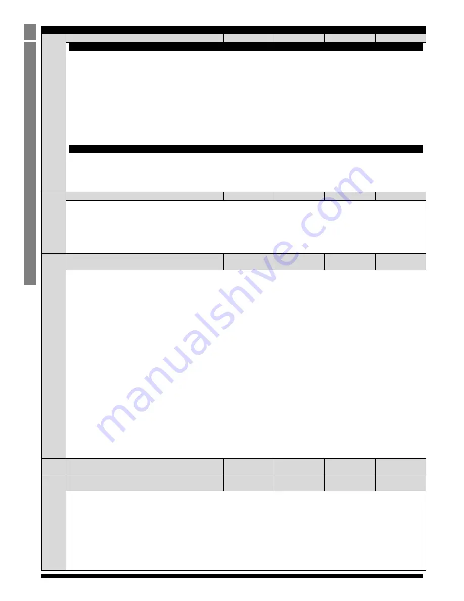
P2-13
Analog Output 2 (Terminal 11) Function Select
0
12
9
-
Digital Output Mode. Logic 1 = +24V DC
0 : Drive Enabled (Running)
. Logic 1 when the Optidrive is enabled (Running)
1 : Drive Healthy
. Logic 1 When no Fault condition exists on the drive
2 : At Target Frequency (Speed)
. Logic 1 when the output frequency matches the setpoint frequency. Hysterisis is applied, defined by
P6-04.
3 : Output Frequency > 0.0
. Logic 1 when the motor runs above zero speed. Hysterisis is applied, defined by P6-04.
4 : Output Frequency >= Limit
. Logic 1 when the motor speed exceeds the adjustable limit
5 : Output Current >= Limit
. Logic 1 when the motor current exceeds the adjustable limit
6 : Output Toque >= Limit
. Logic when the motor torque exceeds the adjustable limit
7
: Analog Input 2 Signal Level >= Limit
. Logic when the signal applied to the Analog Input 2 exceeds the adjustable limit
Note
: When using settings 4 – 7, parameters P2-16 and P2-17 must be used together to control the behaviour. The output will switch
to Logic 1 when the selected signal exceeds the value programmed in P2-16, and return to Logic 0 when the signal falls below the value
programmed in P2-17.
Analog Output Mode
8 : Output Frequency (Motor Speed)
. 0 to P-01
9 : Output (Motor) Current
. 0 to 200% of P1-08
10 : Motor Torque
. 0 to 200% of motor rated torque
11 : Output (Motor) Power
. 0 to 200% of drive rated power
12 : PID Controller Output.
0 – 100% of PID Controller Output
P2-14
Analog Output 2 (Terminal 11) Format
-
-
-
= 0 to10V.
= 10 to 0V,
= 0 to 20mA
= 20to 0mA
= 4 to 20mA
= 20 to 4mA
P2-15
User Relay 1 Output (Terminals 14, 15 & 16) Function
select
0
14
1
-
Selects the function assigned to Relay Output 1. The relay has three output terminals, Logic 1 indicates the relay is active, and
therefore terminals 14 and 15 will be closed together.
0
: Drive Enabled (Running)
. Logic 1 when the motor is enabled
1 : Drive Healthy
. Logic 1 when power is applied to the drive and no fault exists
2
: At Target Frequency (Speed)
. Logic 1 when the output frequency matches the setpoint frequency. Hysterisis is applied, defined by
P6-04.
3 : Output Frequency > 0.0 Hz
. Logic 1 when the drive output frequency to the motor is exceeds 0.0Hz. Hysterisis is applied, defined by
P6-04.
4
: Output Frequency >= Limit
. Logic 1 when the motor speed exceeds the adjustable limit
5
: Output Current >= Limit
. Logic 1 when the motor current exceeds the adjustable limit
6
: Output Torque >= Limit
. Logic 1 when the motor torque exceeds the adjustable limit
7
: Analog Input 2 Signal Level >= Limit
. 1 Logic when the signal applied to the Analog Input 2 exceeds the adjustable limit
8 : No Function
9 : No Function
10 : Service Due
. Logic 1 when the user settable maintenance time (P6-24) has expired. This allows the user to set a service interval
time, for example in the even where a machine requires a defiend service time interval for maintenance, the drive can provide visual
indication of the maintenance interval.
11 : Drive Ready to Run
. Defined as not in inhibit mode, hardware enable present, not in mains loss condition and no trip.
12 : Drive Tripped.
Logic 1 when the drive has
tripped and the display shows a fault.
13 : STO Status.
Logic 1 when the STO inputs are present, and the drive is not in inhibit state
Note
: When using settings 4 – 7, parameters P2-16 and P2-17 must be used together to control the behaviour. The output will switch
to Logic 1 when the selected signal exceeds the value programmed in P2-16, and return to Logic 0 when the signal falls below the value
programmed in P2-17.
14 : PID Error >= Limit.
Logic 1 when the PID Error exceeds the adjustable threshold
P2-16
Adjustable Threshold 1 Upper Limit (Analog Output 1 /
Relay Output 1)
P2-17
200.0
100.0
%
P2-17
Adjustable Threshold 1 Lower Limit (Analog Output 1 /
Relay Output 1)
0.0
P2-16
0.0
%
Used in conjunction with some settings of Parameters P2-11 & P2-15.


