


12
| Optidrive ODE-3 User Guide |
Version 1.00
www.invertekdrives.com
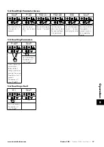
Shield Termination (Cable Screen)
The safety ground terminal provides a grounding point for the motor cable shield. The motor cable shield connected to this terminal
(drive end) should also be connected to the motor frame (motor end). Use a shield terminating or EMI clamp to connect the shield to
the safety ground terminal.
4.3. Incoming Power Connection
4.3.1. Cable Selection
For 1 phase supply, the mains power cables should be connected to L1/L, L2/N.
For 3 phase supplies, the mains power cables should be connected to L1, L2, and L3. Phase sequence is not important.
For compliance with CE and C Tick EMC requirements, refer to section 4.9. EMC Compliant Installation on page 15.
A fixed installation is required according to IEC61800-5-1 with a suitable disconnecting device installed between the Optidrive
and the AC Power Source. The disconnecting device must conform to the local safety code / regulations (e.g. within Europe,
EN60204-1, Safety of machinery).
4.3.2. Fuse / Circuit Breaker Selection
Suitable fuses to provide wiring protection of the input power cable should be installed in the incoming supply line, according to
the data in section 9.2. Rating Tables. The fuses must comply with any local codes or regulations in place. In general, type gG (IEC
60269) or UL type J fuses are suitable; however in some cases type aR fuses may be required. The operating time of the fuses must
be below 0.5 seconds.
Where allowed by local regulations, suitably dimensioned type B MCB circuit breakers of equivalent rating may be utilised in
place of fuses, providing that the clearing capacity is sufficient for the installation.
The maximum permissible short circuit current at the Optidrive Power terminals as defined in IEC60439-1 is 100kA.
4.3.3. Optional Input Choke
An optional Input Choke is recommended to be installed in the supply line for drives where any of the following conditions occur:
o The incoming supply impedance is low or the fault level / short circuit current is high.
o The supply is prone to dips or brown outs.
o An imbalance exists on the supply (3 phase drives).
o The power supply to the drive is via a busbar and brush gear system (typically overhead Cranes).
In all other installations, an input choke is recommended to ensure protection of the drive against power supply faults. Part numbers
are shown in the table.
Supply
Frame Size
AC Input Inductor
230 Volt
1 Phase
1
OPT-2-L1016-20
2
OPT-2-L1025-20
3
N/A
400 Volt
3 Phase
1
OPT-2-L3006-20
2
OPT-2-L3010-20
3
OPT-2-L3036-20
4
OPT-2-L3050-20
5
OPT-2-L3090-20
4.4. Motor Connection
The drive inherently produces fast switching of the output voltage (PWM) to the motor compared to the mains supply, for motors
which have been wound for operation with a variable speed drive then there is no preventative measures required, however if the
quality of insulation is unknown then the motor manufacturer should be consulted and preventative measures may be required.
The motor should be connected to the Optidrive U, V, and W terminals using a suitable 3 or 4 core cable. Where a 3 core cable
is utilised, with the shield operating as an earth conductor, the shield must have a cross sectional area at least equal to the phase
conductors when they are made from the same material. Where a 4 core cable is utilised, the earth conductor must be of at least
equal cross sectional area and manufactured from the same material as the phase conductors.
The motor earth must be connected to one of the Optidrive earth terminals.
Maximum permitted motor cable length for all models: 100 metres shielded, 150 metres unshielded.
Where multiple motors are connected to a single drive using parallel cables, an output choke
must
be installed.
Power & Contr
ol Wiring
4


