


Hardware Operations
2015-MNU-000006
2-1
2
Hardware Operation
This chapter provides the detailed information and replacement steps for motherboard,
including system battery, processor, system memory, and system configuration jumper.
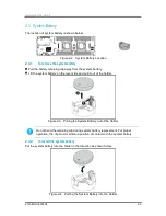
2.1
Before You Start
Take note of the following precautions before you remove and install any components on the
motherboard.
Reminder
Before you remove or install the components on motherboard please follow the steps below:
Step 1: Make sure the server is not turned on or connected to the AC power.
Step 2: Remove the chassis cover.
Moving the Power On/Off switch to the Off position does not completely remove
system power. Some portions of the power supply and some internal circuitry remain
active. Disconnect all power cords from the server to remove all power from the
system.
•
The components shown in this chapter are mainly for your reference. Please take
the actual shipment as standard.
•
All descriptions in this chapter are based on one motherboard except special
statement.
To reduce the risk of injury from electric shock, remove the power cord to completely
disconnect power from the system.
Summary of Contents for B900G3
Page 1: ...Board Manual B900G3 August 2015 Revision A P N 2015 MNU 000006 ...
Page 3: ......
Page 8: ......
Page 18: ......
Page 28: ......
Page 29: ......
Page 30: ......
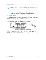
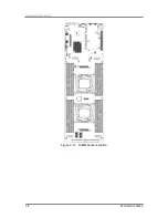
Page 38: ...Hardware Operations 2015 MNU 000006 2 8 Figure 2 13 DIMM Socket Location ...
Page 42: ......
Page 56: ......
Page 57: ...Appendix China RoHS Regulations ...
Page 58: ......
Page 59: ......
Page 60: ......


