background image

Setup

4.23 Center-mounted legrests — manually
adjustable

4.23.1 Removing the legrest

You can remove central, manually adjustable legrest
completely.

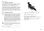
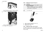
1.

Remove removable axle (1).

2.

Hold legrest securely and pull lever (1).

3.

Remove legrest from holder (2).

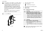
4.23.2 Setting the angle of the leg rest

CAUTION!
Risk of injury

If the leg rest is not secured and the lever (1) is
removed, the leg rest will drop suddenly, which
could cause an injury.

– Secure the leg rest before you remove the lever

to adjust the angle of the leg rest.

1.

Hold the leg rest securely.

2.

Pull the lever (1).

3.

Push the leg rest into the required position.

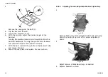
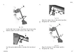
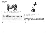
4.23.3 Setting Length of Legrest

3/16 inch Allen key

You can adjust the length of the legrests independently of
one another.

1656515-B

41

Summary of Contents for Modulite

Page 1: ...lite Supplement to power wheelchair user manual en Seating System User Manual This manual MUST be given to the user of the product BEFORE using this product this manual MUST be read and saved for futu...

Page 2: ...whole or in part is prohibited without prior written permission from Invacare Trademarks are identified by and All trademarks are owned by or licensed to Invacare Corporation or its subsidiaries unles...

Page 3: ...Armrest Height Following Armrest 22 4 12 Changing Resistance Flip Up Following Armrest 22 4 13 Adjusting Arm Pad Angle Flip Up Following Armrest 23 4 14 Adjusting Arm Pad Position Flip Up Armrest 23 4...

Page 4: ...Unlocking and swivelling the calf pad backward when alighting 57 4 27 7 Adjusting the angle adjustable foot plate 58 4 27 8 Adjusting the angle and depth adjustable foot plate 58 4 28 Powered elevatin...

Page 5: ...in This Manual Symbols and signal words are used in this manual and apply to hazards or unsafe practices which could result in personal injury or property damage See the information below for definiti...

Page 6: ...the power wheelchair including the seating system Be certain to read and follow these safety information WARNING Risk of Tipping The power wheelchair may tip over when you change its stability charac...

Page 7: ...our stability while driving refer to Safety Lockout and Limit Switches DX System The wheelchair has a programmable controller which allows adjustment of the maximum acceleration and deceleration of th...

Page 8: ...to help secure and position clients legs In addition we offer a multitude of legrest hangers to accommodate your legrest choice Power legrests may be programmed to operate in one of the two following...

Page 9: ...Model Tilt Angle x Lifter Lockout AVIVA RX 20 50 mm Max Back Angle Limit The maximum back angle limits how far the backrest can be reclined using either the tilt or recline actuators The seating syst...

Page 10: ...gle Wheelchair Model Height Backrest Angle AVIVA RX 50 mm 130 Drive Lockout DLO Limit All tilt and recline seating systems are equipped with a drive lockout DLO limit to prevent the wheelchair from be...

Page 11: ...ice and before use make sure that all attaching hardware is present and tightened securely WARNING Risk of Injury or Damage Incorrect set up of this mobility device performed by users caregivers or un...

Page 12: ...ibility for Remote The following information is valid for all seating systems CAUTION Risk of the remote being pushed backwards during an accidental collision with an obstacle such as a doorframe or t...

Page 13: ...rews A 2 Adjust component to desired position 3 Tighten screws 4 2 3 Adjusting Remote Height only for Swing Away Remote Supports 6 mm Allen key Fig 4 3 1 Loosen screw A 2 Adjust component to desired p...

Page 14: ...component to desired position 3 Tighten screws 4 3 Adjusting Swing Away Display Holder Adjusting Holder Height 3 mm Allen key 1 Loosen screws A 2 Position holder to desired height 3 Tighten screws Ad...

Page 15: ...ientation 3 Tighten clamping bush 4 4 Adjustment Possibilities for Nucleus Midline Holder WARNING Risk of Injury or Death Loose small parts can lead to choking hazard that may result in injury or deat...

Page 16: ...just the height of the nucleus midline holder in two ways Adjust it together with the armrest height Refer to corresponding armrest chapters Adjust the height of the nucleus midline holder only Refer...

Page 17: ...y Fig 4 9 1 Loosen screw A 2 Position display on nucleus 3 Tighten screw DLX CR400 and DLX CR400LF Tilting Remote 4 mm Allen key Fig 4 10 1 Loosen screws A 2 Position remote on nucleus 3 Tighten screw...

Page 18: ...ng screw A 2 Adjust component to desired position 3 Tighten wing screw 4 6 Adjusting Armrest Width WARNING Serious injury hazard if one of the armrests falls out of its bracket because they have been...

Page 19: ...ding on the side the screw is accessible from the front or the rear 8 mm Allen key Fig 4 16 1 Loosen screw A 2 Adjust component to desired position 3 Tighten screw 4 7 Adjusting Armrest Depth 6 mm All...

Page 20: ...ities CAUTION Risk of Injury and Damage Remaining burrs and missing end caps after modifications on rods such as shortened rod can lead to injury or damage Deburr cut after cutting excessive length Re...

Page 21: ...Height Refer to Adjusting Swing Away Mechanism 4 8 2 Adjusting Egg Switch Adjusting Switch Orientation The egg switch can be turned through 360 degrees 7 16 inch wrench Fig 4 20 1 Loosen nut A 2 Adju...

Page 22: ...ust component to desired position 3 Tighten thumb screw 4 11 Adjusting Armrest Height Following Armrest Tools 5 mm Allen key 13 mm wrench Fig 4 23 1 Loosen and remove screw A and nut B 2 Adjust compon...

Page 23: ...Adjusting Arm Pad Angle Flip Up Following Armrest Tools 5 mm Allen key Fig 4 25 1 Loosen screws A Do not remove screws A 2 Adjust component to desired position 3 Tighten screws 4 14 Adjusting Arm Pad...

Page 24: ...port from holder Inserting hip support 1 Insert hip support in holder 2 Push lever A downwards Ensure that hip support locks with an audible click Adjusting position of hip support Risk of damage If t...

Page 25: ...red position 3 Tighten screw Adjusting width of hip support 2 x 5 mm Allen key 1 Loosen screws A 2 Adjust hip support to desired width You can adjust the width only smaller than the seat width but not...

Page 26: ...ten screws Adjusting hip pad depth 10 mm wrench 1 Loosen the two screws A 2 Adjust hip pad to desired depth 3 Tighten screws Adjusting hip pad height You can adjust the hip pad height in two ways Via...

Page 27: ...3 Insert hip pad bracket in other mounting slot 4 Tighten screws Via bracket 5 mm Allen key 1 Remove upper screw and friction cap A 2 Remove small friction link B 3 Remove hip pad with bracket turn up...

Page 28: ...This impacts its dynamic stability If you make a major change to the seat depth the centre of gravity of the seat must also be adjusted See Adjusting the centre of gravity of the seat in the service...

Page 29: ...describes the procedures for adjusting the height of the backrest plate The sling back is only available in fixed heights of 48 and 54 cm 5 mm Allen key Fig 4 29 1 Loosen screws A and B Do not remove...

Page 30: ...not remove screws B 3 Adjust component to desired position 4 Insert screw A 5 Tighten screws 4 18 3 Adjusting Backrest Angle CAUTION Every change to the seat angle and the backrest angle alters the g...

Page 31: ...holes of backrest bracket Screw must be visible on inside of bracket and screw head must be flush with bracket Simple Backrest 6 mm Allen key Fig 4 32 1 Loosen and remove middle backrest screw A on bo...

Page 32: ...ti clockwise and outwards inclines the backrest forwards 7 With the bolt reattach the spindle to the backrest tube and secure the bolt 8 Mount the seat plate and replace the seat cushion 4 18 5 Adjust...

Page 33: ...different adjustments according to how the backrest is mounted Position A the part of the backrest with the longer angle turned upwards gives the user more room for the shoulder area while position B...

Page 34: ...acare Modulite 3 Loosen the screws B and remove the backrest by lifting upwards 4 Turn the backrest 180 5 Put the backrest back by fitting it to the receivers on the tubes Tighten the screws 34 165651...

Page 35: ...d or not installed This can cause the neck to be hyperextended during collisions A headrest must be installed The headrest optionally supplied for this mobility device by Invacare is perfectly suitabl...

Page 36: ...eadrest left or right to the required position 6 Retighten the Allen screw 4 19 2 Adjusting Height of Rea Headrest or Neckrest The adjustment of the height is the same for all Rea headrests and neckre...

Page 37: ...use during transport The headrest must be adjusted to the user s ear height Fig 4 37 It may be necessary to remove and modify the back cushion cover in order to access the headrest mounting holes on t...

Page 38: ...desired angle via the pivot ball at the end of the headrest rod by loosening and tightening the mounting hardware 3 Loosen and remove lower D Ring E from hardware 4 Slide vertical mounting post B int...

Page 39: ...Tighten screws and clamping levers 4 21 Adjusting Trunk Supports 4 21 1 Adjusting Width Fig 4 41 1 Loosen knobs A that hold lateral supports 2 Adjust component to desired position 3 Tighten knobs 4 21...

Page 40: ...nent to desired position 3 Tighten wing screw 4 22 2 Adjusting Depth of Tray Removing Tray Fig 4 46 1 Loosen wing screw A 2 Adjust component to desired position or remove it entirely 3 Tighten wing sc...

Page 41: ...the leg rest CAUTION Risk of injury If the leg rest is not secured and the lever 1 is removed the leg rest will drop suddenly which could cause an injury Secure the leg rest before you remove the lev...

Page 42: ...ain 4 23 5 Setting Angle and Height of Calf Pad 3 16 inch Allen key Fig 4 49 1 Fold the calf pad forward in order to access the bolt 1 2 Loosen the bolt using the Allen key and adjust the calf pad to...

Page 43: ...of legrest It may be necessary to remove the nuts and move them from one slot to the other 4 Set desired length 5 Retighten nuts 6 Refit the calf pads and cover and retighten screws The legrest with f...

Page 44: ...ers nor the seat plate when adjusting the legrest angle Calf pads may be adjusted independently on their respective mounting bracket using the mounting screws at the rear of the calf pads Calf pads ma...

Page 45: ...an upward direction 4 25 2 Setting the angle CAUTION Risk of injury due to incorrect adjustment of the footrests and legrests Before and during every journey it is imperative to ensure that the legres...

Page 46: ...angle 5 Re tighten the screw 4 25 3 Setting the end stop of the footrest 6 mm Allen key 10 mm wrench 1 Fig 4 52 The end position of the footrest is determined by means of a rubber stop 1 2 Fig 4 53 Th...

Page 47: ...upward in order to access the rubber stop 4 Fig 4 55 Use the open ended spanner to loosen the counternut 1 5 Fig 4 56 Move the rubber stop to the desired position 6 Re tighten the counternut 7 Fig 4...

Page 48: ...e screw 1 2 Adjust to the desired length 3 Re tighten the screw 4 26 Vari A legrests 4 26 1 Swivelling the footrest legrest outward and or removing The small unlocking button is located on the upper s...

Page 49: ...of the footrests and legrests Before and during every journey it is imperative to ensure that the legrests contact neither the castor wheels nor the ground 1 Loosen the locking knob 1 counter clockwi...

Page 50: ...n the knob clockwise to tighten it 4 26 3 Setting the end stop of the legrest 10 mm wrench 1 The end position of the legrest is determined by means of a rubber stop 1 2 The rubber stop can be screwed...

Page 51: ...locking knob 1 counter clockwise at least one turn 4 Hit the knob to release the locking mechanism 5 Swivel the legrest upward in order to access the rubber stop 6 Use the wrench to loosen the counter...

Page 52: ...ent of the footrests and legrests Before and during every journey it is imperative to ensure that the legrests contact neither the castor wheels nor the ground 5 mm Allen key 1 Use the spanner to loos...

Page 53: ...rew and the oblong holes for the aglet without thread 3 Screw the nut back on and tighten 4 26 6 Adjusting the height of the calf pad 4 mm Allen key 1 Use the Allen key to loosen the screws 1 2 Adjust...

Page 54: ...justable foot plate 5 mm Allen key 1 Use the Allen key to loosen both set screws on the foot plate 2 Adjust to the desired angle 3 Re tighten the screws 4 26 9 Adjusting the angle and depth adjustable...

Page 55: ...ss the unlocking button 1 and swivel the footrest legrest outward 2 Remove the footrest legrest in an upward direction 4 27 2 Setting the angle CAUTION Risk of crushing Do not reach inside the swivell...

Page 56: ...legrests Before and during every journey it is imperative to ensure that the legrests contact neither the castor wheels nor the ground 5 mm Allen key 1 Use the spanner to loosen the screw 1 2 Adjust...

Page 57: ...d the oblong holes for the aglet without thread 3 Screw the nut back on and tighten 4 27 5 Adjusting the height of the calf pad 4 mm Allen key 1 Use the Allen key to loosen the screws 1 2 Adjust to th...

Page 58: ...justable foot plate 5 mm Allen key 1 Use the Allen key to loosen both set screws on the foot plate 2 Adjust to the desired angle 3 Re tighten the screws 4 27 8 Adjusting the angle and depth adjustable...

Page 59: ...each inside the swivelling range of the legrest CAUTION Risk of injury due to incorrect adjustment of the footrests and legrests Before and during every journey it is imperative to ensure that the leg...

Page 60: ...e wrench to loosen the nut 1 and remove 2 Adjust to the desired depth Observe that the round holes are intended for the calf pad retaining screw and the oblong holes for the aglet without thread 3 Scr...

Page 61: ...le foot plate 5 mm Allen key 1 Use the Allen key to loosen both set screws on the foot plate 2 Adjust to the desired angle 3 Re tighten the screws 4 28 8 Adjusting the angle and depth adjustable foot...

Page 62: ...o facilitate access and also be removed completely Fig 4 59 1 Push release lever inward or outward 2 Adjust component to desired position 3 Pull upward to remove component 4 29 2 Adjusting Length Stan...

Page 63: ...64 6 7469 9 32 7 1438 19 64 7 5406 5 16 7 9375 21 64 8 3344 11 32 8 7313 23 64 9 1281 IMPERIAL METRIC inch mm 3 8 9 5250 25 64 9 9219 13 32 10 3188 27 64 10 7156 7 16 11 1125 29 64 11 5094 15 32 11 90...

Page 64: ...IAL METRIC inch mm 43 64 17 0656 11 16 17 4625 45 64 17 8594 23 32 18 2563 47 64 18 6531 3 4 19 0500 49 64 19 4469 25 32 19 8438 51 64 20 2406 13 16 20 6375 53 64 21 0344 27 32 21 4313 55 64 21 8281 7...

Page 65: ...est support B from bearing plate C 2 Fig 5 3 Flip up armrest for side transfer For more information about side transfer see the user manual of the mobility device 5 2 Swivelling Remote to Side Fig 5 4...

Page 66: ...der only locks in place when swivelled to its default position 1 Push knob A and swivel display holder to side 5 5 Removing inserting hip support with quick release Removing hip support 1 Pull lever A...

Page 67: ...ering footboard when it touches the floor You can lower the telescoping footboard until a preset point Depending on the wheelchair configuration this point might not exactly fit the seat to floor heig...

Page 68: ...stem is operating properly and safely Invacare recommends a complete dealer inspection be performed on your power positioning system every six 6 months by a qualified technician Be certain to read and...

Page 69: ...s and regulations for waste handling in each country Contact your local waste management company for information 7 2 Reconditioning This product is suitable for reuse To recondition the product for a...

Page 70: ...rs not engaged Engage drive motors Wheelchair power is ON but system does not drive LNX powered center mounted legrest with telescoping footboard lowered Retract footboard to top position Low batterie...

Page 71: ...exhausted battery fluctuating charge Check replace battery Contact your provider Loose faulty electrical connection Check connections Contact your provider DLO limit switch mechanical switch is not se...

Page 72: ...our provider Low voltage Contact your provider System only operates in one direction Battery not charged Charge batteries Remote not plugged in Inspect cable connection Remote not turned on Turn on po...

Page 73: ...ual of your wheelchair Dimensions Modulite Seating System Power Wheelchair Dimensions According to ISO 7176 15 TDX SP2 AVIVA RX Seat Width Armrest Adjustment Range in Parentheses 380 mm 380 430 mm 430...

Page 74: ...piece seat plate 275 340 325 390 mm T armrest Armrest Depth max 440 mm 325 mm Armrest Length 325 397 mm Seat Angle Electrical Adjustment 30 0 30 5 25 with 5 fixed anterior mount 0 30 Seat Angle Elect...

Page 75: ...90 mm 460 mm ADM manual Angle 80 0 Length 350 mm 450 mm Standard 80 Angle 80 0 Length 280 mm 385 mm Centre Mounted manual Angle 90 0 Length 340 mm 410 mm Centre Mounted Powered LNX Angle 97 7 90 0 83...

Page 76: ...in Tel 353 1 810 7084 Fax 353 1 810 7085 ireland invacare com www invacare ie New Zealand Invacare New Zealand Ltd 4 Westfield Place Mt Wellington 1060 New Zealand Phone 0800 468 222 Fax 0800 807 788...

Reviews: