Open-Q™ 624A Development Kit
Open-Q™ 624A Development Kit User Kit
40
3.8.18
GNSS Front-end and Antennas
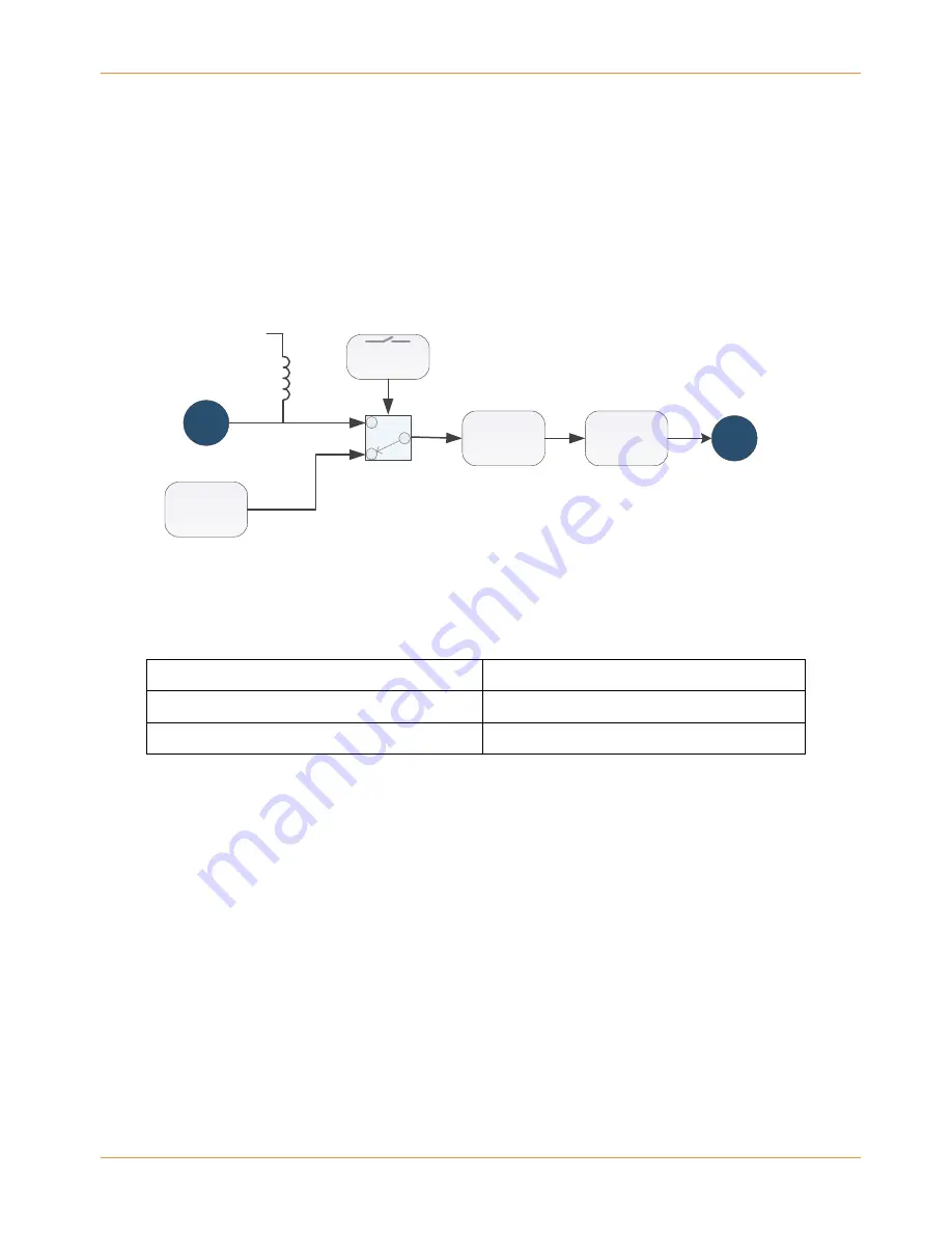
The Open-Q™ 624A carrier board includes a GNSS RF front-end circuit as well as a PCB trace antenna and
an SMA type external antenna connector. The RF front-end circuit includes an LNA and a SAW filter for
improved performance and an antenna switch to enable connection to either the PCB trace antenna or the
SMA external antenna connector. Depending on which antenna is used, DIP switch S10 must be configured
correctly (see Table 3-14 below for details).
PCB Antenna
SMA
Filter
LNA
Antenna
switch circuit
U.FL
GPS_LNA_VDD (2.7V)
To the Open-Q 624A SOM
Switch S10A
External GPS Antenna
connection
Figure 19 GNSS Front-end block diagram.
Table 3-14 GNSS Antenna Selection Switch
GPS Antenna Selection [GPS_CTRL1] DIP Switch S10 (Position 1) Selection
On Board PCB Antenna
OFF
External Antenna
ON
PCB Trace Antenna:
Note that the PCB trace antenna has relatively low performance and will generally only
provide sufficient signal quality if there is a clear open view of the sky. Otherwise, a better, external antenna
connected to the SMA connector will be required.
Use of External Antenna:
A passive or active antenna may be connected to the SMA external antenna
connector, but it is recommended to use an active antenna unless the antenna cable is very short, or the
antenna is connected directly to the SMA connector. If the antenna cable is long, the signal loss through the
cable will seriously degrade the signal level unless an active antenna is used. The antenna port is biased with
2.7v specifically for powering an active antenna so make sure to select an antenna that can operate from
2.7v.
Evaluation of GNSS Receiver Performance:
Note that the performance of the GNSS receiver will be
affected significantly by the following factors:
•
Whether or not an active antenna is used
•
The gain and directionality of the antenna
•
Whether the RF front-end of the carrier board is used.


